NOVATECH INSTRUMENTS 9 409C Manual Rev 1.12
filters should have a sharp roll off at or below about 40%
of the synthesizer clock frequency. When using External
Reference or Direct Input clocks the user should use the
“Q” command to find the synthesizer clock frequency
and if it is much below 429MHz then consider using ex-
ternal filters at about 40% of the synthesizer clock fre-
quency.
4.9 Phase Alignment. Phase relationships are main-
tained by appropriate use of the “M” and “I” commands.
The “M” command has special modes “M a” and “M n”.
“M a” means automatically clear phase at the end of each
command. This will clear the phase register each time
any command is performed. This is important when all
outputs must be phase aligned. However, it will cause a
phase jump in the output.
4.10 Phase Synchronous. The “M n” command turns
off the automatic clearing of the phase register. This is
the default mode. In this mode, the phase register is left
intact when a command is performed. Use this mode if
you want frequency changes to remain phase synchro-
nous, with no phase discontinuities. The “M s” command
will immediately align the phases on all outputs but will
also cause a one time phase discontinuity.
4.11 Command Execution. Further control of phase
relationships and timing of command execution can be
exercised by using the “I x” commands. The default
mode is automatic (x=a) in which a command is parsed
and executed immediately following the end of the serial
input sequence. In manual mode (x=m), an update pulse
will not be sent to the DDS chip automatically. This is
useful when it is important to change all the outputs to
new values simultaneously. Use external triggering or
the “I p” command to cause a manual update. Sending “I
x” where x=e, x=s or x=d controls the function of the
IOUD and TS control logic. (See Section 9)
4.12 Amplitude Matching. For applications which re-
quire precise amplitude matching between the channels,
the recommended method is to use the “Vn x.xxx” com-
mand to adjust the channels to match.
4.13 Table Mode. The Model 409C contains Flash
memory capable of storing up to 14249 rows of data in a
table format. Each row can specify the frequency, phase
and amplitude of each channel in any combination of
channels. Any channels that are not specified in a row
will not change when the row is run. The row also stores
a dwell time that specifies how long the channel settings
specified by the row are held before stepping to the next
row. The dwell time is only used when running the ta-
ble.
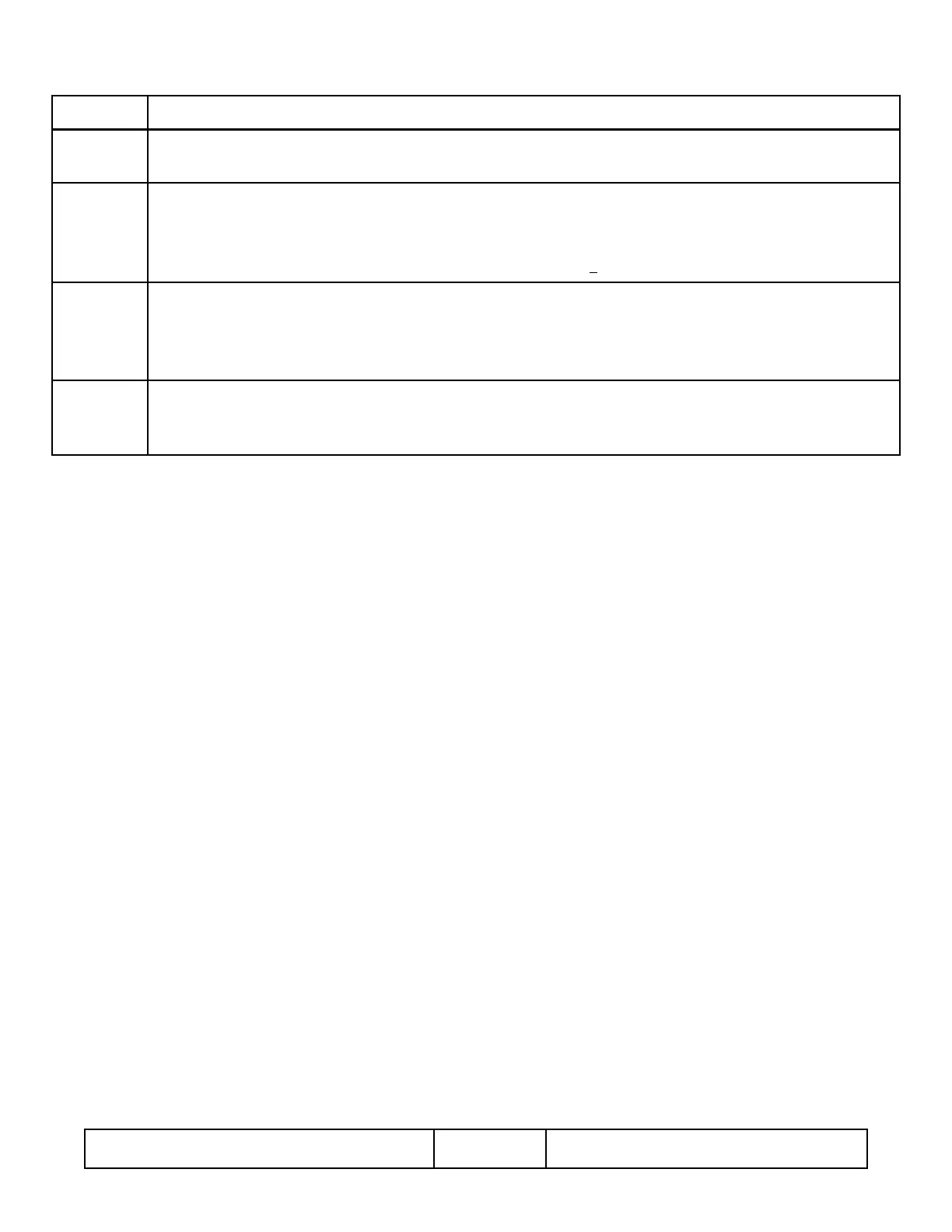
Command Source of Synthesizer Clock
C i Selects Internal Clock. The Synthesizer Clock is the Internal TCXO oscillator stepped up by the AD9959 clock mulpli-
er. The clock mulplier is automacally set by 409C microcontroller firmware. (When Opon /R is NOT installed )
C i Selects Internal Clock. The Synthesizer Clock is the TCXO oscillator on the /R daughter board stepped up by the
AD9959 clock mulplier. The user must apply a 10MHz signal at the rear panel BNC and this signal disciplines the
TCXO oscillator to improve the frequency accuracy. The clock mulplier is automacally set by 409C microcontroller
firmware. (When Opon /R is installed and a user supplied 10MHz +5ppm signal is applied to the rear panel BNC)
C e Selects External Reference Clock. The Synthesizer Clock is the frequency stored by the Fr xxx.xxxxxx command
stepped up by the AD9959 clock mulplier. The user must apply a signal with frequency Fr xxx.xxxxxx to the rear
panel BNC connector. The AD9959 clock mulplier is automacally set by the 409C microcontroller firmware. The
accepted frequency range for Fr is 10.000000 MHz to 125.000000 MHz.
C d Selects External Direct Clock. The Synthesizer Clock is the frequency stored by the Fd xxx.xxxxxx command. The user
must apply a signal with frequency Fd xxx.xxxxxx to the rear panel BNC connector (SMA connector if Opon E is in-
stalled) The accepted frequency range for Fd is 1.000000 MHz to 500.000000 MHz. The AD9959 mulplier is 1.
Table 5 Synthesizer Clock
 Loading...