Do you have a question about the Novatel OEM7700 and is the answer not in the manual?
Steps to take before contacting support for software issues, including data logging.
Explains GNSS positioning principles and the role of INS in enhancing accuracy and continuity.
Details the configurable features and models of SPAN system receivers.
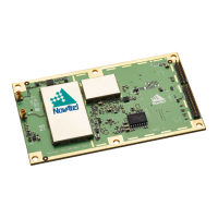
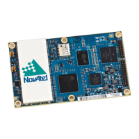
Provides guidance on installing the OEM7 receiver card and connecting system components.
Provides instructions for mounting the GNSS antenna for optimal signal reception.
Details the procedure for mounting the IMU to ensure constant orientation and distance.
Explains connection methods for various IMUs to the OEM7 receiver card.
Provides instructions for connecting power to the IMU and receiver for operation.
Guides the installation of the MEMS Interface Card (MIC) for connecting IMUs.
Details mounting the MIC card directly onto an OEM719 receiver.
Explains how to mount the MIC separately from the OEM7 receiver.
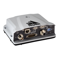
Guides the installation of the Universal IMU Controller (UIC) for connecting IMUs.
Instructions for mounting the antenna, receiver, and UIC for the SPAN system.
Details the connection procedure for the IMU to the UIC interface.
Explains how to connect the UIC's serial port to the OEM7 receiver.
Provides steps for connecting power to the UIC and the OEM7 receiver.
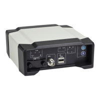
Provides instructions for installing the PwrPak7 for SPAN systems.
Details connecting the IMU to the COM1 or COM2 serial port on the PwrPak7.
Provides instructions for installing the PwrPak7-E1 for SPAN systems.
Guides the installation of a wheel sensor for distance measurement.
Lists the requirements for compatible wheel sensors used with PwrPak7 and IMUs.
Explains how to connect wheel sensors to PwrPak7, IMU, or UIC.
Explains how SPAN combines GNSS and INS, requiring knowledge of component offsets.
Defines translational offsets between IMU and other SPAN components.
Defines rotational offsets representing orientation differences between IMU and components.
Details the software configuration steps for both the GNSS receiver and IMU.
Outlines the minimum required information to configure a SPAN system.
Explains setting up GNSS configuration for various accuracy levels.
Describes INS Profiles for simplified configuration and enhanced performance.
Guides manual configuration of the SPAN system using software commands.
Explains how SPAN operates through the OEM7 command and log interface.
Details the system alignment process required to start the navigation filter.
Describes using saved INS information to quickly initialize the system at startup.
Explains the navigation mode where SPAN computes position, velocity, and attitude.
Lists available logs for INS solution and other parameters.
Guides calibration of the lever arm when the system is re-mounted or moved.
Details calibration for the rotational offset between IMU Body and Vehicle frames (RBV).
Provides a method for higher roll offset accuracy in vehicle frame calibration.
Explains how to synchronize the SPAN system with external equipment using input pulses.
Describes attaching and triggering external sensors using OEM7 receiver connections.
Guides the configuration of wheel sensors for distance measurement and updates.
Explains how the PwrPak7 collects wheel sensor data and uses it for updates.
Describes how IMU-CPT, iIMU-FSAS, and IMU-IGM collect and pass wheel sensor data.
Explains the three methods used by SPAN systems to calculate azimuth.
Details data collection requirements for post-mission processing of SPAN data.
Explains the concept of variable lever arms for gimballed mounts.
Details how to use the variable lever arm functionality with gimbal angles input.
Explains NovAtel's Relative INS technology for generating vectors between SPAN systems.
Guides the configuration of receivers to compute relative information.
Details the hardware installation for SPAN systems with dual antennas.
Guides the configuration of the ALIGN solution for SPAN systems.
Explains how to configure SPAN for different alignment routines based on motion conditions.
Describes how INS heading updates constrain azimuth drift of the INS solution.
Provides physical specifications for the MEMS Interface Card (MIC).
Provides physical specifications for the Universal IMU Controller (UIC).
Procedure for installing the HG1700 sensor unit into the Universal Enclosure.
Procedure for installing the HG1700 sensor unit into the SPAN HG Enclosure.
Procedure for installing the LN-200 sensor unit into the Universal Enclosure.
Procedure for installing the LN-200 sensor unit into the SPAN IMU Enclosure.
Details the minimum configuration commands required to start the SPAN system.