Chapter2 Connection
Manual of NVEC400
- 15 -
2.2.6 5th axis extend port
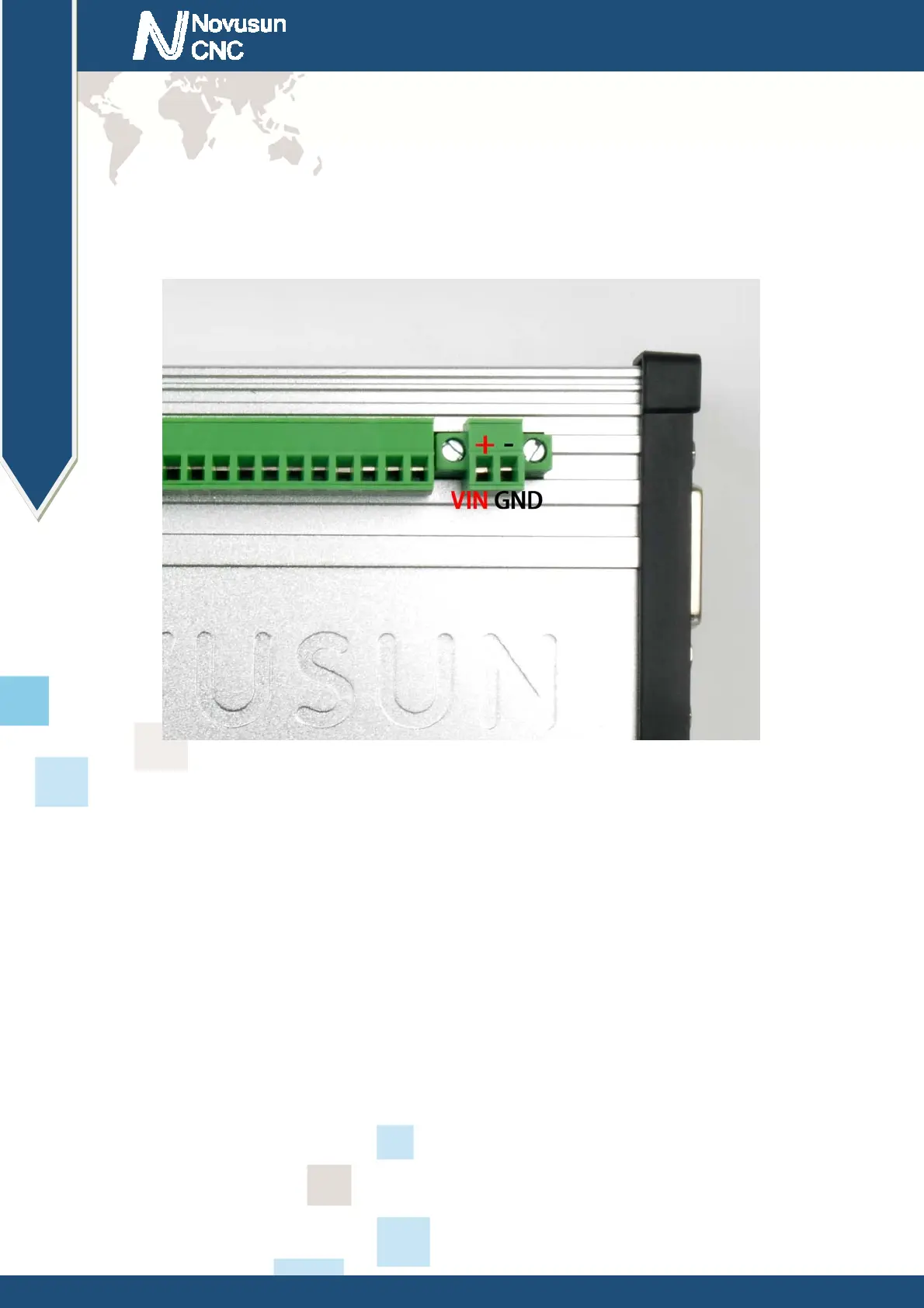
As the Figure 2-2 show, The marked No. 6 port is power supply port. The access voltage
range is 12-36V, and the power demand is not less than 20W. As shown in the picture, the left
terminal is power + and the right terminal is power - see as Figure 2-10.
Figure2-10. Power port
2.2.7 Limit/Home input port
As the Figure 2-2 showed, Marked No. 7 position is the limited /home input port. they are
the optical isolated Input interface. The Definition from left to right is IN1 IN2 GNDIN IN3 IN4
IN5 IN6 IN7 GNDIN VIN IN8 IN9 IN10 IN11 IN12 IN13 IN14 IN15 IN16 GNDIN VIN . Internal
structure see as Figure2-11. 2 lines Proximity Switch/ordinary fretting switch / drawing see as
Figure2-12.
www.nvcnc.net
 Loading...