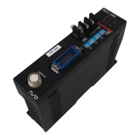
6-3. Input / Output Connector Connection
Lead wires should be soldered to pins of the connector according to the I/O chart below.
Pin
No.
Signal Names
Input /
Output
Descriptions
1
D0
2
D1
3
D2
4
D3
5
D4
6
D5
7
D6
8
D7
9
D8
10
D9
11
D10
12
D11
13
D12
Output
NCV-20NBNVP:
Output the position data by 13 bit of binary code.
NCV-20NGNVP:
Output the position data by 13 bit of gray binary code.
D0
:LSB(Least Significant Bit)
D12
:MSB(Most Significant Bit)
14
15
16
17
NC
Do not connect anything.
18 SE
Switches OFF when sensor or connector is disconnected or
loose.
19
SE
Sensor
disconnected error
Output
Switches ON when sensor or connector is disconnected or
loose.
20 Z24 SE ground Ground for sensor disconnected error output signal
21 P24 24V
This is a power supply for the sensor disconnected error output
and HOLD input signals.
22
HD
HOLD
Input
The HOLD input signal is used to HOLD position data outputs
from the host controller.
23
LP
Latch pulse Output Outputs the position data reading timing signal.
24 SG Signal ground
25 SG Signal ground
Input
Ground for
D0
to
D12
, and
LP
signals
(LSB)
Position data
(MSB)
Connector at cable side (It is included in the converter.) Soldered socket: MR-25F
Cover: MR-25L
Connectors are manufactured by Honda Tsushin Kogyo Co., LTD.
Pin arrangement
18
 Loading...