APPENDICES 2. VE-2A(G) AND NCV-20 COMPATIBILITY
In the case of replacing VE-2A(G) with NCV-20, please refer to the following contents.
Appendix 2-1. Procedure of Replacing VE-2A(G) with NCV-20
The following chart indicates the procedure of replacing VE-2A(G) with NCV-20.
Procedure Description
1) Check the position data. - Check the VE-2A(G) position data before the replacement.
2) Remove VE-2A(G) - Remove VE-2A(G)
3) Confirm and set the
position data "increase
direction" switch
- Set the position data “increase direction” switch of NCV-20 to "CCW", if there is
"CCW" on the name plate of VE-2A(G).
(There is no description on the name plate when the position data “increase
direction” switch is “CW”.)
- In the case of the position data “increase direction” is unknown (or there is a
possibility that the direction might be changed.)
・Remove VE-2A(G) cover, and check whether slide switch is at “CCW”
or "CW" on the printed circuit board, then set the direction of position data
“increase direction” switch of NCV-20 to same direction as VE-2A(G).
4) Set the function setting
switch
- Set DIP switch on a rear face of NCV-20 as shown in figure below.
・Position data update cycle: 0.2ms
・Position data reading by HOLD (HD) input: Transparent format
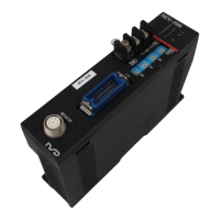
5) Mount NCV-20 -Mount NCV-20.
6) Set the current position
setting of NCV-20
- Correct the current position value of NCV-20 to the same value as checked in
procedure 1 by using "current position setting function".
Please refer to the section "8-4. Current position setting" for the setting process
of current position setting.
32
 Loading...