Do you have a question about the NSD Varicam VS-5E-1 and is the answer not in the manual?
Covers handling, storage, transport, installation, operation, and maintenance safety guidelines.
Explains signal words, graphic symbols, and application limitations.
Provides instructions for the safe disposal of the controller.
Provides an overview and features of the VS-5E Series electronic cam switch.
Contains comprehensive specifications for controllers, sensors, and cables.
Details physical dimensions, mounting, and available models.
Guides on how to install the controller and sensor safely.
Information on power supply, controller, and sensor connections.
Explains the electronic cam switch format and its advantages over mechanical systems.
Lists the main features like easy setting, compact design, and durability.
Details available controller, sensor, and extension cable types.
Describes how switch outputs correspond to rotational angle and multi-dog settings.
Explains how to protect switch settings from unintended changes.
Details current position value and timing pulse outputs for speed detection.
Describes origin point setting via external signal and teach function.
Explains how to hold current position and output statuses.
Details the use of RS-232C for setting backup and communication.
Lists general parameters like voltage, power, temperature, and weight.
Details position detection, setting units, speed, programs, and outputs.
Specifies formats and voltages for Program No. and HOLD inputs.
Details formats and voltages for switch, timing, and BCD outputs.
Provides internal circuit diagrams for input and output signals.
Details dimensions, torque, inertia, and environmental specs for VRE-P062 and VRE-P028.
Lists types, construction, temperature range, and lengths of extension cables.
Provides detailed dimensional drawings for VS-5E and VS-5E-1 controllers.
Provides detailed dimensional drawings for VS-5ED and VS-5ED-1 controllers.
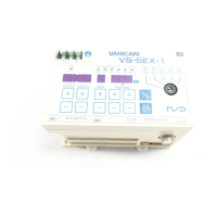
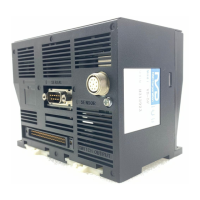
Provides dimensional drawings for VS-5EX and VS-5EX-1 controllers.
Details dimensions for the VS-K05 panel mounting fixture.
Shows dimensions and mounting holes for VRE-P062SAC/SBC sensors.
Details mounting fixture dimensions for reinforced servo mounts.
Provides dimensions and mounting holes for VRE-P062FAC/FBC sensors.
Details dimensions for the RB-01 L-type flange mounting option.
Shows dimensions and mounting holes for the VRE-P028SAC sensor.
Details the dimensions of standard and robotic extension cables.
Shows the dimensions of the VS-C05 external cable.
Lists available controller and sensor models with their descriptions.
Details available extension cables, fixtures, and external cables.
Verifies all controller and sensor components are present upon delivery.
Guidelines for safely mounting the controller.
Guidelines for safely mounting the sensor.
Specifies environmental conditions required for controller installation.
Lists precautions for securing the controller and ensuring proper installation.
Safety guidelines for handling the sensor to prevent damage from drops or shocks.
Instructions for positioning the cable port and routing the cable.
Describes shaft coupling and gear linkage procedures for sensor mounting.
Details mounting procedures for rack-and-pinion and chain/pulley linkages.
Guidance on the optimal position for attaching the shaft to the coupling or gear.
Factors to consider when selecting a coupling device based on machine design.
Safety and best practices for installing coupling devices to avoid damage.
Instructions for connecting the power supply, including cable thickness and grounding.
Guidance on connecting the controller to the sensor using standard or extension cables.
Identifies the switch output and BCD connectors and their uses.
Lists input and output signals and their applicable models.
Shows internal circuits for switch, System Ready, timing pulse, and program outputs.
Illustrates internal circuits for Program No. and HOLD inputs.
Details pin assignments and cable colors for the switch output connector.
Details pin assignments for the BCD connector used for program and position data.
Details pin assignments for the VS-5EX switch output connector.
Details pin assignments for the VS-5EX BCD connector.
Pin assignments for the VS-5EX 32-program, 24-switch output connector.
Pin assignments for the VS-5EX 32-program, 24-switch BCD connector.
Illustrates timing for Program No. input and switch output signals.
Shows timing for current position output and latch pulse signals.
Explains timing when the HOLD input is active for position output.
Illustrates timing for external origin set input and switch output.
Outlines the steps for initial setup and designation of parameters.
Describes the process for designating switch output settings.
Details the steps for executing the operation after settings are made.
Lists the five core operations required for the VS-5E Series to become operative.
Instructions for powering on the VS-5E Series using an external switch.
Guides on designating the direction of angular value increase for the sensor.
Describes how to move the machine and designate the origin point.
Steps for selecting the program and switch number for output settings.
Procedure for designating the ON position value for a switch output.
Procedure for designating the OFF position value for a switch output.
Steps to select the desired program and enter RUN mode.
How to display the ON/OFF status of switch outputs in RUN mode.
Introduces the initial settings required for VALICAM functions.
Covers setting sensor direction and VS-5EX output specifications.
Details setting the origin point and program input format.
Configuring SET mode, output HOLD, and timing pulse settings.
Setting latch pulse cycle, communication format, and baud rate.
Designating output logic for current position or speed signals.
Steps to designate the initial number for settings.
Procedure for setting the content for basic initial settings.
Procedure to designate 16-Program/40-Switch or 32-Program/24-Switch format.
Steps to designate Initial No. 96 and password to activate the Protected Switch function.
Steps to designate Initial No. 96 and password to cancel the Protected Switch function.
Procedure to numerically input and set the current position value.
Steps to set the ON position using the TEACH function and machine movement.
Steps to set the OFF position using the TEACH function and machine movement.
Procedure to set up to 10 ON/OFF points for each output using multi-dog settings.
Steps to cancel multi-dog settings by designating dog number and value.
Steps to cancel settings for a switch number and subsequent ones.
How to view current position and setting values in RUN mode.
How to display the ON/OFF status of switch outputs in RUN mode.
Procedure for changing setting values in 0.5-degree increments while in RUN mode.
How to view the ON/OFF statuses of multiple switch outputs simultaneously.
Table detailing error causes, displays, and countermeasures for common errors.
Required settings after replacing the sensor or controller unit.
| Port Speed | 10/100/1000Mbps |
|---|---|
| MAC Address Table | 8K |
| Switching Capacity | 10Gbps |
| Forwarding Rate | 7.44Mpps |
| Ports | 5 |
| Storage Temperature | -40°C to 70°C |