Do you have a question about the NSD Varicam VS-5E Series and is the answer not in the manual?
Guidelines for safely handling the controller to prevent electric shock and damage.
Recommendations for storing the controller to maintain its condition and longevity.
Precautions to take when transporting the controller and sensor to prevent injury or damage.
Safety measures for installing the controller and sensor, ensuring proper mounting and clearance.
Safety instructions for wiring the controller, emphasizing terminal security and cover usage.
Safety guidelines for operating the controller, including precautions during power failure and emergency stops.
Safety advice regarding maintenance and repair, including avoiding disassembly.
Instructions for the safe and compliant disposal of the controller as industrial waste.
Overview of the VS-5E Series electronic cam switch format replacing mechanical systems.
Details general specifications for VS-5E, VS-5ED, VS-5EX controller models.
Provides specifications for VRE-P062 and VRE-P028 sensor models.
Details specifications for standard and robotic extension cables.
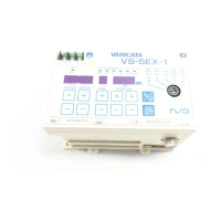
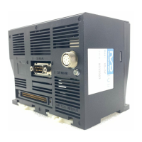
Diagrams and dimensions for VS-5E, VS-5ED, and VS-5EX controller units.
Provides outer dimensions and mounting details for VRE-P062 and VRE-P028 sensors.
Shows outer dimensions for standard and robotic extension cables.
Lists available controller models (VS-5E, VS-5ED, VS-5EX) with their programs and voltage.
Lists available sensor models (VRE-P062, VRE-P028) with their specifications.
Lists available extension cable models with lengths and types.
Details panel-mount fixtures, reinforced servo mounting fixtures, and external cables.
Procedure to verify that all controller and sensor components are present in the shipping case.
Guidelines and precautions for installing the controller unit, including site and installation requirements.
Guidelines and precautions for handling and mounting the sensor unit.
Describes methods for mounting the sensor shaft using couplings, gears, racks, and pulleys.
Details on connecting the power supply for 100VAC and 24VDC models, including grounding.
Instructions for connecting the controller to the sensor using extension cables.
Identifies connectors and describes their functions for controller models.
Lists and describes input and output signals for VS-5E, VS-5ED, and VS-5EX models.
Flowchart for designating initial settings like sensor rotation and output specifications.
Flowchart for designating switch output settings using angle input or TEACH function.
Flowchart step for executing the operation after settings are designated.
Procedure and notes for switching the VS-5E Series controller power ON using an external switch.
Steps to designate the sensor rotation direction where angular value increases.
Procedure to designate the origin point position by moving the machine and setting it as 'zero'.
Detailed steps for setting ON and OFF positions for switch outputs using the SET key-switch.
Instructions for operating the VS-5E Series in RUN mode and checking switch output status.
Introduces the necessity and process of designating initial settings for VALICAM functions.
Lists initial setting numbers, items, descriptions, settings, and applicable models.
Step-by-step guide for performing basic initial settings using the key-switch and display.
Procedure for setting output specifications for VS-5EX models immediately after delivery.
Steps to enable the Protected Switch function, which prevents unauthorized setting changes.
Procedure to cancel the Protected Switch function and allow setting changes.
Method to set the current position value numerically without moving the machine.
Instructions for setting switch ON and OFF positions using the TEACH function.
Procedure to set multiple ON/OFF points (multi-dog) for each output using TEACH or SET.
Method to cancel multi-dog settings by designating the dog number and setting value.
Procedure to cancel settings for a specific switch number and all subsequent numbers.
How to display and verify switch output ON/OFF status during RUN mode.
Procedure to fine-tune setting values in 0.5-degree increments while in RUN mode.
Simultaneously displays ON/OFF statuses of multiple switch outputs in RUN mode.
Table listing error displays, causes, and recommended countermeasures for controller malfunctions.