Do you have a question about the NSD VARILIMIT VS-12PB and is the answer not in the manual?
Explains DANGER/CAUTION symbols and graphic symbols used in the manual.
Specifies limitations for product use and environmental categories.
Safety precautions for handling, storing, and transporting the controller.
Safety precautions for electrical wiring and physical installation.
Safety guidelines for operating, maintaining, and disposing of the unit.
Information on diagnosing and resolving operational issues and errors.
Contains supplementary data sheets and reference materials for settings.
Provides a general introduction to the VS-12PB controller and its applications.
Describes the basic system configuration and components of the VS-12PB.
Outlines the main functions and capabilities of the VS-12PB controller.
Details the key features and capabilities of the VS-12PB positioning controller.
Illustrates the typical system setup with the VS-12PB and its accessories.
Explains how to set positions for various positioning operations.
Describes the automatic positioning process based on sensor feedback.
Details the unidirectional positioning method to minimize backlash errors.
Explains the speed switching format for positioning control.
Describes the speed stepping format for positioning control.
How to initiate operation from within the STOP zone.
Configuration of motion non-detection and misdirection timers.
How the learning function adjusts stop positions for accuracy.
Fine positioning control using short ON/OFF switching.
Manual positioning control by key inputs or external signals.
Demonstrates how limit switch outputs replace conventional switches.
Prevents unauthorized changes to limit switch output settings.
Shows an application of the preset function in a transport system.
Illustrates controlling multiple VS-12PB units via a host controller.
Explains various self-diagnosis functions for error detection.
Covers the technical specifications of the VS-12PB controller.
Provides physical dimensions and mounting information for the controller.
Details how to order the VS-12PB and its related accessories.
Lists general electrical, environmental, and physical specs of the VS-12PB.
Details performance-related specs like axes, functions, and timing.
Specifies details for control and BCD input/output signals.
Technical specifications for MRE 2-phase multi-turn sensors.
Technical specifications for MRE 3-phase multi-turn sensors.
Technical specifications for Linear Type VLS sensors.
Details sensor cable models, characteristics, and compatible sensors.
Shows dimensional drawings for the VS-12PB controller.
Illustrates the dimensions and mounting for the OVS-K12 option.
Shows dimensions for servo and reinforced servo-mount fixtures for MRE sensors.
Details flange mounting hole dimensions for MRE sensors.
Provides dimensions for MRE 3-phase sensors and mounting.
Shows dimensional drawings and stroke lengths for VLS sensors.
Lists VLS sensor models with detection stroke and dimensions.
Illustrates dimensions for various cable types (4S-RBT, 4P-S, 3S-RBT).
Shows dimensions for VS-T12/T12B connecting and communication cables.
Illustrates typical configurations for different sensor types.
Lists part numbers and models for controllers, sensors, and accessories.
Details the steps involved in wiring the VS-12PB controller.
Covers the necessary steps for installing the VS-12PB controller.
Lists components to check upon receiving the VS-12PB unit.
Specifies environmental and physical requirements for controller installation.
Provides installation notes for rotary type ABSOCODER sensors.
Provides installation notes for linear type ABSOCODER sensors.
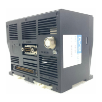
Identifies terminals and connectors on the VS-12PB.
Specifies requirements for using crimp type terminals.
Explains how to connect the power supply (100/120VAC).
Shows terminal assignments and signal names for control I/O.
Explains the function of each control signal.
Illustrates a typical wiring example for control signals.
Provides detailed descriptions for each input/output signal.
Shows timing charts for various control signals during operations.
Identifies pins for BCD connectors and lists signal names.
Explains the names and descriptions of BCD signals.
Describes timing for reading BCD output via latch pulse or DTC input.
Details pin assignments and shows circuit diagrams for communication.
Illustrates how to connect the ABSOCODER sensor cable.
Provides precautions for routing and securing sensor cables.
Outlines the procedures for operating the VS-12PB controller.
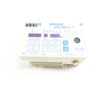
Identifies the parts and layout of the VS-12PB control panel.
Explains the functions of the display area and status indicators.
Describes the operation of the control keys on the panel.
Details how control keys function in different operating modes.
Explains the selection of modes using the key-switch.
Outlines the standard sequence for operating the VS-12PB.
Important notes and potential errors during power on.
Step-by-step guide for setting basic initial parameters.
Configures sensor rotation, decimal point, and selects the sensor type.
Defines scale length, min/current position values for detection.
Details the procedure for setting sensor rotation direction (CW/CCW).
Step-by-step guide to setting the decimal point.
Procedure for selecting the appropriate sensor type.
Guides on calculating and inputting the scale length.
Procedure to set the minimum value for current position display.
How to set the machine's starting current position.
Configures multi-drop communication, slave numbering, and specs.
Configures brake monitoring, count display, and data downloading.
Parameters for controlling dual speed positioning operations.
Step-by-step guide to accessing and changing parameters.
Settings for motion detection timers and operational zones.
Parameters for upper/lower limits and correction amounts.
Settings for protected switches and limit output status selection.
Parameters for PRE functions, output timing, and preset values.
Describes operations performable in TEST mode.
Overview of positioning control and limit switch outputs in RUN mode.
Step-by-step guide for AUTO positioning in TEST mode.
Procedures for setting target positions for AUTO positioning in RUN mode.
Steps to start and execute AUTO positioning in RUN mode.
How to perform JOG operation in TEST mode.
How to perform JOG operation in RUN mode.
Steps to configure ON/OFF positions for limit switch outputs.
Methods for setting limit switch ON/OFF points via teaching or input.
How to enable and configure limit switch output in TEST mode.
Procedure for designating protected switch channels.
Steps to delete dog output settings for a specific channel.
How to add new dog output ON/OFF position settings.
Steps to delete limit switch output settings in channel units.
How to delete limit switch outputs in batch by program units.
Steps to copy program data to and from a host controller.
How to use the password function to protect settings.
Steps to delete all data and restore initial settings.
Information for diagnosing and resolving common issues.
Supplementary materials including data sheets.
Lists error codes, causes, and recommended countermeasures.
Details error codes related to zones, overshoot, programs, and motion.
Covers errors like inching, direction, PRE, and output malfunctions.
Explains how to reset errors using external input or panel keys.
Summary of initial settings for sensor, decimal, scale, and position.
Details initial settings for communication and brake monitoring.
Lists parameters for positioning, zones, and motion detection.
Parameters for INCHING, speed control, limits, and switch outputs.
Parameters for PRE functions, output timing, and preset values.
Template for setting limit switches via communication.
Template for setting limit switches via panel key input.