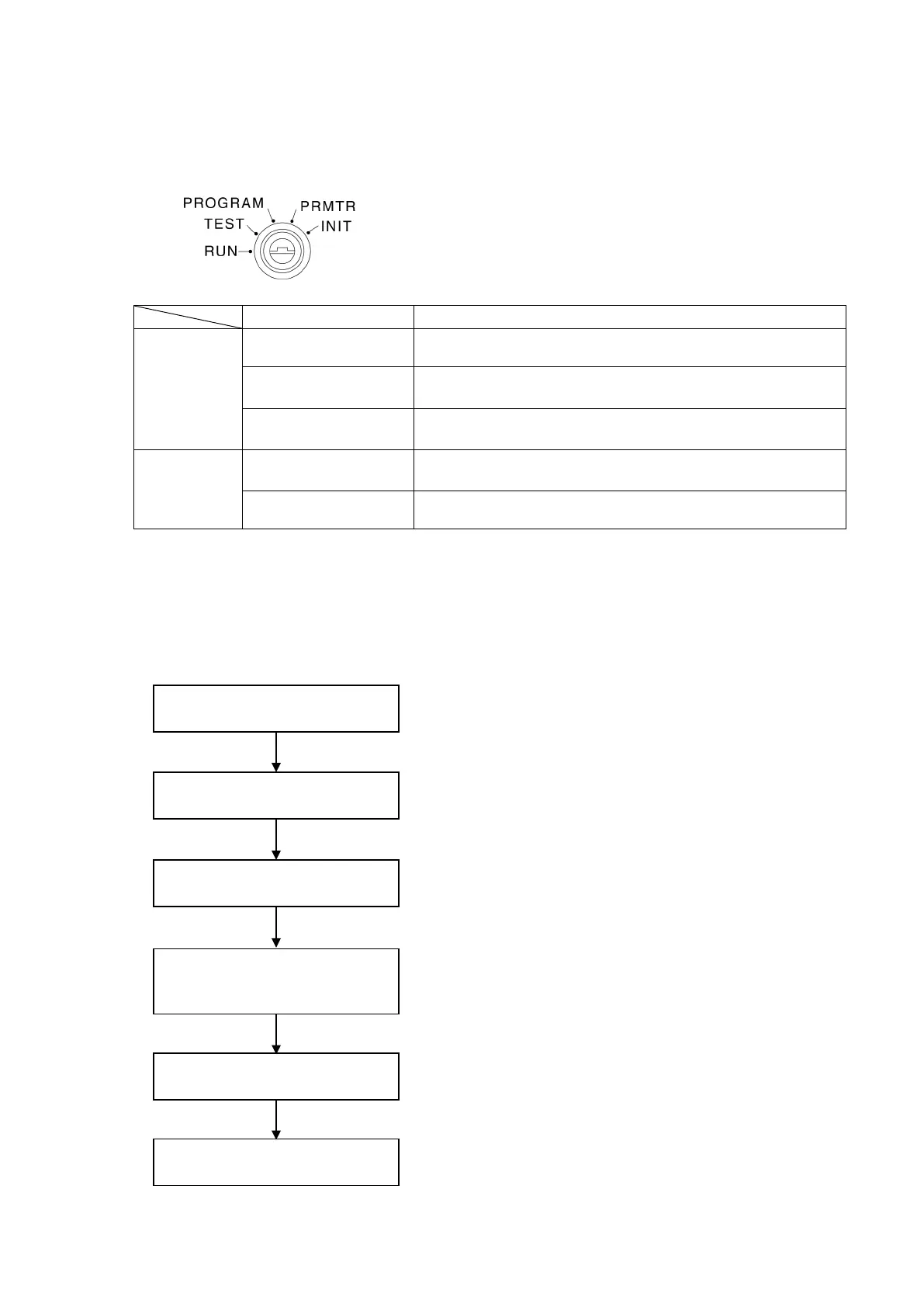
③ Mode Key-Switch
This switch is used to designate any one of the 5 modes described below.
These modes can be divided into 2 main categories : Setting modes, and Operation modes.
Mode Description
Setting Modes
INIT (Initial Setting)
The INIT mode is used to designate the initial settings required for VS-12PB
operation (communication specs., sensor selection, scale length, etc.).
PRMTR Mode
(Parameter Setting)
The PRMTR mode is used to designate the parameter settings required for
VS-12PB positioning control, and for the limit switch output function.
PROGRAM Mode
The PROGRAM mode is used to designate and edit the target stop position
and limit switch output data.
Operation Modes
TEST (Test Run)
The TEST mode is used to execute a trial runs for each of the positioning
operations (AUTO, INCH, JOG) from the VS-12PB control panel.
RUN
The RUN mode is used to execute positioning control and limit switch output
operation.
9-1-2. Operation Sequence
The basic VS-12PB operation sequence is shown below.
1. Switch the power ON, and verify that there is no sensor
error,etc.
2. Designate the initial setting required for VS-12PB operation.
(Sensor rotation direction, sensor selection, etc.)
3. Designate the parameter settings required for VS-12PB
positioning and limit switch output operations.
4. Designate the target stop positions for AUTO positioning, and
the limit switch output data settings.
5. Execute a trial run for the designated setting data.
6. Execute the positioning operation.
Power ON
Initial Settings
(INIT mode)
Parameter Settings
(PRMTR mode)
Limit SW Data Settings