EasyManuals Logo

NSD VARILIMIT VS-12PB User Manual

Default Icon
94 pages
To Next Page IconTo Next Page
To Previous Page IconTo Previous Page
Page #47 background imageLoading...
Page #47 background image
8-7
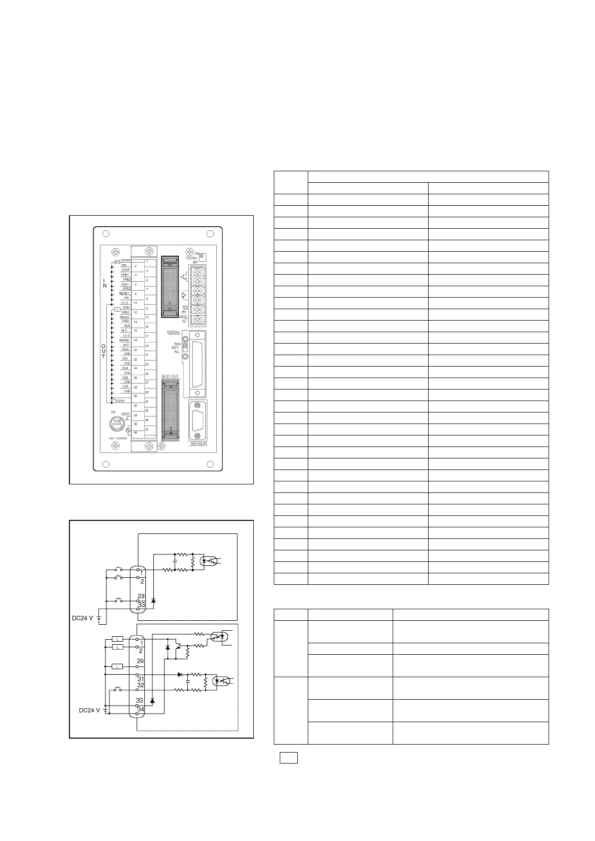
8-1-3. BCD Input / Output Connections
The BCD input / output connections are as shown below. The VS-12PB[ ]-D Model is equipped with this BCD
input / output function.
Connector Pin layout Signal Names
Model: MR-34RMA
The same model is used for both the input
and output connectors.
Circuit Diagram
Pin
No.
Signal Name
BCD Input connector
BCD Output connector
1
BCD INPUT 1×1
BCD OUTPUT 1×1
2
BCD INPUT 1×2
BCD OUTPUT 1×2
3
BCD INPUT 1×4
BCD OUTPUT 1×4
4
BCD INPUT 1×8
BCD OUTPUT 1×8
5
BCD INPUT 10×1
BCD OUTPUT 10×1
6
BCD INPUT 10×2
BCD OUTPUT 10×2
7
BCD INPUT 10×4
BCD OUTPUT 10×4
8
BCD INPUT 10×8
BCD OUTPUT 10×8
9
BCD INPUT 100×1
BCD OUTPUT 100×1
10
BCD INPUT 100×2
BCD OUTPUT 100×2
11
BCD INPUT 100×4
BCD OUTPUT 100×4
12
BCD INPUT 100×8
BCD OUTPUT 100×8
13
BCD INPUT 1000×1
BCD OUTPUT 1000×1
14
BCD INPUT 1000×2
BCD OUTPUT 1000×2
15
BCD INPUT 1000×4
BCD OUTPUT 1000×4
16
BCD INPUT 1000×8
BCD OUTPUT 1000×8
17
BCD INPUT 10000×1
BCD OUTPUT 10000×1
18
BCD INPUT 10000×2
BCD OUTPUT 10000×2
19
BCD INPUT 10000×4
BCD OUTPUT 10000×4
20
BCD INPUT 10000×8
BCD OUTPUT 10000×8
21
BCD INPUT 100000×1
BCD OUTPUT 100000×1
22
BCD INPUT 100000×2
BCD OUTPUT 100000×2
23
BCD INPUT 100000×4
BCD OUTPUT 100000×4
24
BCD INPUT 100000×8
BCD OUTPUT 100000×8
25
Vacant
Vacant
26
Vacant
Vacant
27
Vacant
Vacant
28
Minus symbol input
Minus symbol output
29
Vacant
Latch pulse output
30
Vacant
Vacant
31
Vacant
DTC input +
32
Vacant
DTC input -
33
24VDC +
24VDC +
34
Vacant
24VDC -
Signal Names & descriptions
Signal Name
Description
Input
BCD input
Target stop position is designated by an
external input.
Minus symbol input
A minus symbol input is executed.
DTC input *
A current position value “HOLD” status is
established.
Output
BCD output
The current position value is output in
BCD code.
Minus symbol output
Output occurs when the current position
is a minus value.
Latch pulse output
A timing output to ensure that the current
position value is read while stable.
Note
DTC input signal is connected to the BCD output connector.

Table of Contents

Questions and Answers:

Question and Answer IconNeed help?

Do you have a question about the NSD VARILIMIT VS-12PB and is the answer not in the manual?

NSD VARILIMIT VS-12PB Specifications

General IconGeneral
BrandNSD
ModelVARILIMIT VS-12PB
CategorySwitch
LanguageEnglish

Related product manuals