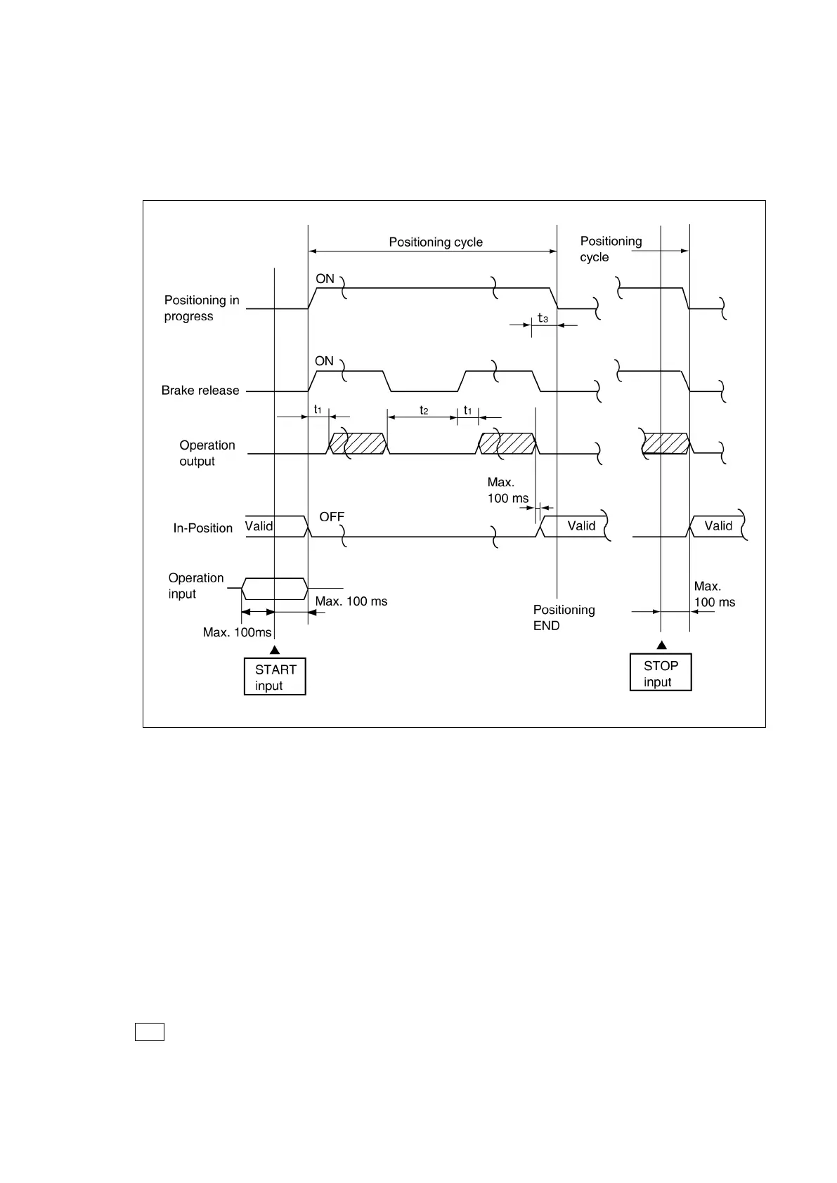
●Control Timing
The timing for each of the control signals is as shown below.
●Control timing for “overshoot” positioning when positioning START signal switches ON:
① The
“
t
1,
t
2, and
t
3”
times shown above represent the following:
t
1
: The delay period from the point when the brake is released, until the point when the operation output
switches ON. (10 ms)
t
2
: The stop time required for a U-turn when overshooting occurs. After the operation switches OFF and
the brake switches ON (occurs simultaneously), a STOP status will be recognized based on the
amount proceed to the next operation.
t
3
: The delay period (after positioning is stopped) fromthe brake ON point, to the pointwhen the RUN
signal goes OFF (positioning completed). This delay period is designated by a parameter setting
(positioning END detection timer).
② During RETRY operations, the RUN signal will not switch OFF.
③ Do not change the operation input within a period of 100 ms before or after the operation START .
Operation input signal: SEL, STOP, OPE1, OPE2, F/R, LOS, BCD
Note
Error No.40 occurs if the operation input signal statuses are changed 100 ms before or after a START input.
 Loading...