9-6. Limit Switch Output Settings
The limit switch output setting procedure is described below.
●Limit Switch Output Setting Conditions
(1) Detection range = Minimum current position value to Minimum current position value + Scale length - 1
(2)
(3) Dog output are designated in ON/OFF pairs.
9-6-1. Limit Switch Settings
Note
When the selected switch No. is protected, cancel the protected switch function.
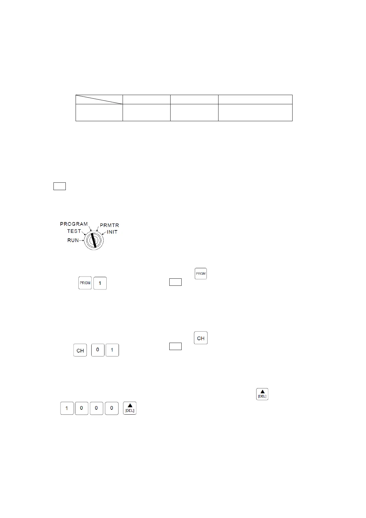
[1] Select the PROGRAM mode.
Turn the mode key-switch to the PROGRAM mode position.
[2] Designate the program No.1
Press the key, then enter “1”
Note
The program No. can be selected from either 0 or 1, but the
setting value of Program No.0 cannot be stored.
Use the program No.0 for checking the communication data.
[3] Designate the desired Channel No. (01-08)
Press the key, then enter the desired Channel No.
Note
A digit input is required. To designate Channel No.1,
for example, enter “01”.
[4] ON position setting.
After ON position setting, press the key to
enter the OFF position setting. At this time, the ON
LED begins flashing, and the OFF LED is switched ON.
No. of Programs No. of Channels No. of Dogs (per CH.)
No. of settings 1 8 10
 Loading...