EasyManuals Logo

NSD VARILIMIT VS-12PB User Manual

Default Icon
94 pages
To Next Page IconTo Next Page
To Previous Page IconTo Previous Page
Page #49 background imageLoading...
Page #49 background image
8-9
8-1-4. Communication Connector (RS-232C, RS-422)
The communication connections are described below.
Notes
- The RS-232C and RS-422 formats cannot be used together.
- Pin No.6 (DSR) and 20 (DTR) connections are inside the VS-12PB.
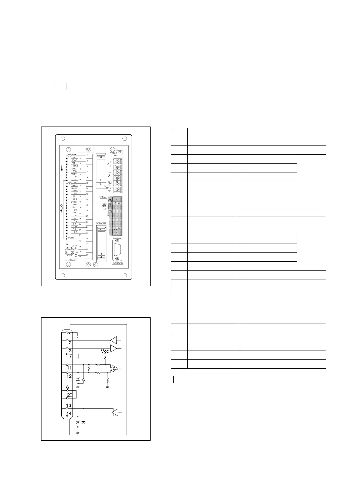
Connector Layout Signal Names
RS-232C / RS-422 Communication Circuit
Connector :DBLC-J25SAF-13L6 (JAE)
Note
Don't connect to unused pins.
Pin
No.
Signal Name Description
1 F.G Shield
2 TXD1 Transmission data
RS-232C
3 RXD1 Reception data
4
RTS
5
CTS
6
(DSR)
7
0V
Signal GND
8
9
10
11
RXD2+
Reception data +
RS-422
12
RXD2-
Reception data -
13
TXD2+
Transmission data +
14 TXD2- Transmission data
-
15
16
17
18
19
20 (DTR) RS-232C
21
22
23
24
25

Table of Contents

Questions and Answers:

Question and Answer IconNeed help?

Do you have a question about the NSD VARILIMIT VS-12PB and is the answer not in the manual?

NSD VARILIMIT VS-12PB Specifications

General IconGeneral
BrandNSD
ModelVARILIMIT VS-12PB
CategorySwitch
LanguageEnglish

Related product manuals