Page 4 of 12
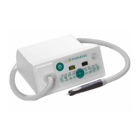
Operating elements and components
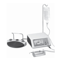
Ill. 1:
(1) Suction chamber
(2) Dust-bag
(3) Front panel
(4) Hand-piece
(5) I/O switch (stand-by) additional to mains switch on the right side
(6) Display for speed
(7) START/STOP pushbutton for the speed of the tool (ROTATION)
(8) Counter-clockwise/ clockwise rotation of the tool (L/R)
(9) Service LED for maintenance
(10) Memory for stored speed values (2x)
(11) Speed control (rotation) (+) = Increase speed (–) = Reduce speed
(12) Display for vacuum power (%)
(13) ON/OFF pushbutton for suction (Vacuum)
(14) Level indicator dust bag
(15) Control of suction capacity (+) = Increase capacity (–) = Reduce capacity
(16) Memory for stored vacuum values (2x)
3
2
1
5
6
8
4
14
15
11
13
12
7
10
16
9
 Loading...