Installation and Operation Instructions Matrix
Operation and Set-up
The Matrix employs a pneumatic modulation system. This modulation system increases or decreases the velocity
of the combustion blower, to meet the demand for heating. The gas valve senses this change in blower pressure
and introduces the required amount of gas to ensure correct combustion. The (Red) Boiler Controller reads the
boiler water temperature, compares it to the set point, and adjusts the burner firing rate accordingly by varying the
speed of the combustion blower.
The (Blue) Fan Controller communicates the appropriate demand and temperature set point to the (Red) Boiler
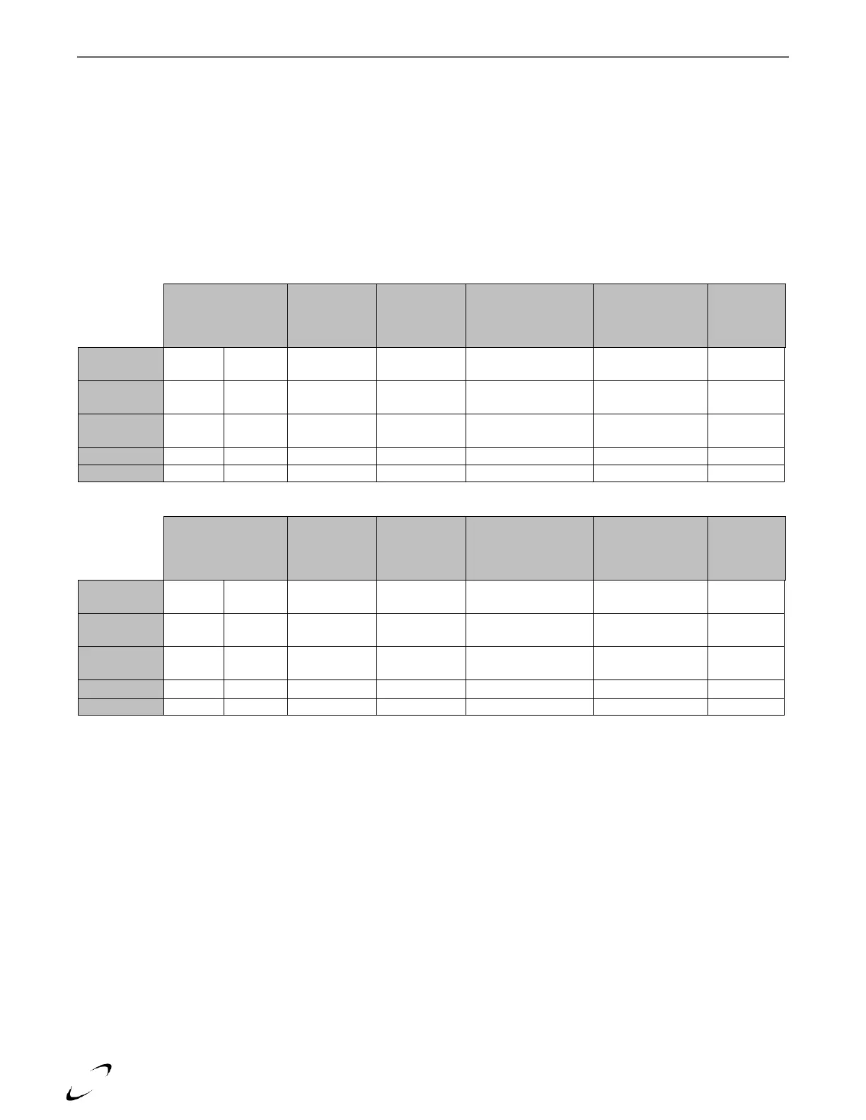
Controller via a series of digital and analog inputs. Tables 13-3(a) and 13-3(b) show the Boiler Controller’s
response to each demand. For more information on ‘RESET MODE’ see section “Outdoor Sensor (10K)”.
Table 13-3(a) Operation – Conventional Mode
Primary
Forced Air
Call (W1)
Auxiliary
Forced Air
Call (W2)
Shared Call
Forced
Air/Hydronic
Greater of SP/ HI
and HYD
Table 13-3(b) Operation – Reset Mode
Primary
Forced Air
Call (W1)
Auxiliary
Forced Air
Call (W2)
Shared Call
Forced
Air/Hydronic
Greater of SP/ HI
Calc.
and HYD
Calc.
Greater of SP/ HI
Calc.
and HYD
Calc.
Note 1: SP (Setpoint) received from Matrix Fan Controller.