NOTES:
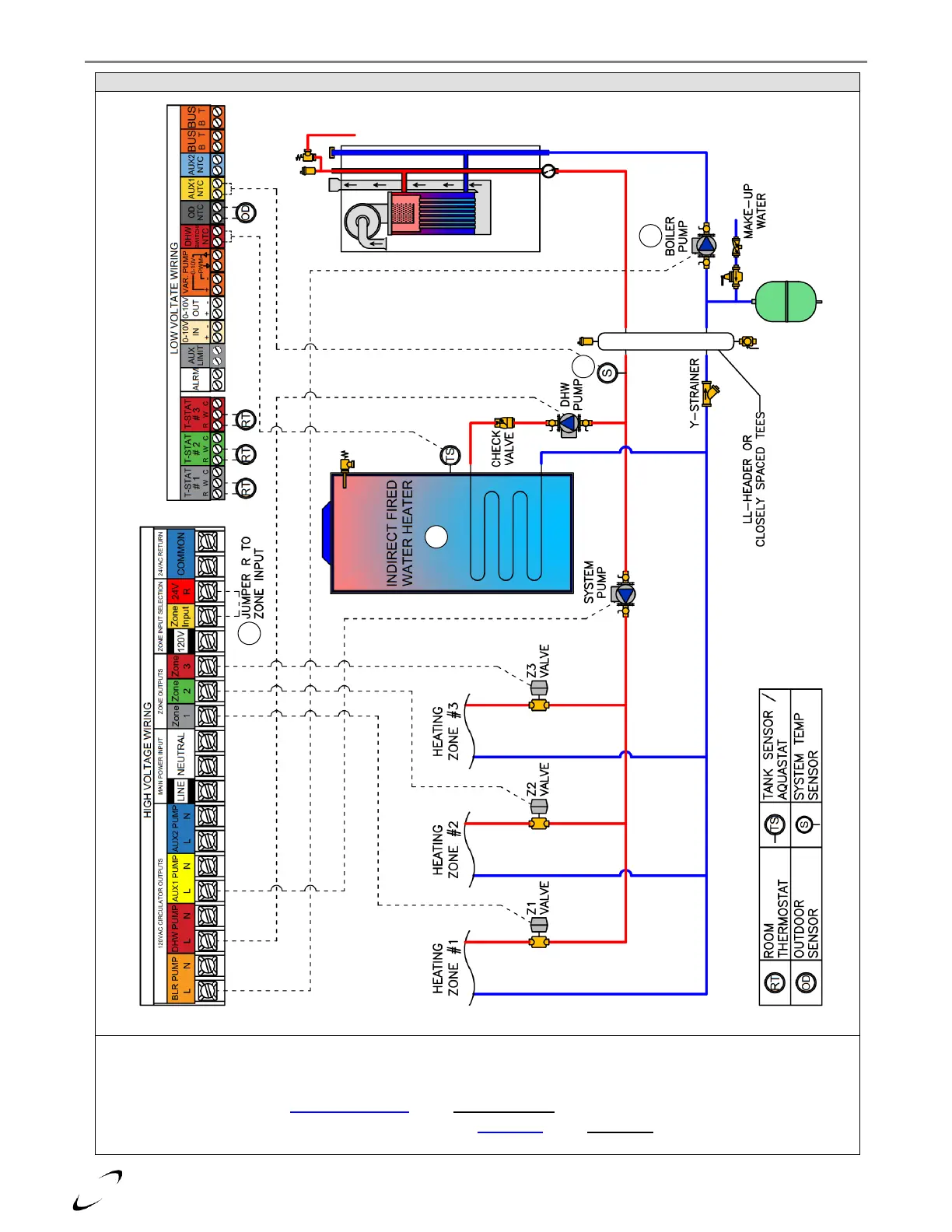
1. For ZONE 1-3 to output 24VAC (like in this example), jumper ZONE INPUT to R (24V)
2. The BOILER PUMP is responsible for circulating water through the boiler, so size accordingly (see Table 10.3).
3. If using a System Sensor, set Sensor Configuration option Auxiliary Sensor 1 (24.6.1) = System Sensor.
4. If application uses a System Sensor, it will be necessary to set DHW Setup option DHW Mode = Downstream IWH (Tank Sensor
or Aquastat); otherwise it is acceptable to be set as Upstream IWH (Tank Sensor or Aquastat).