NOTES:
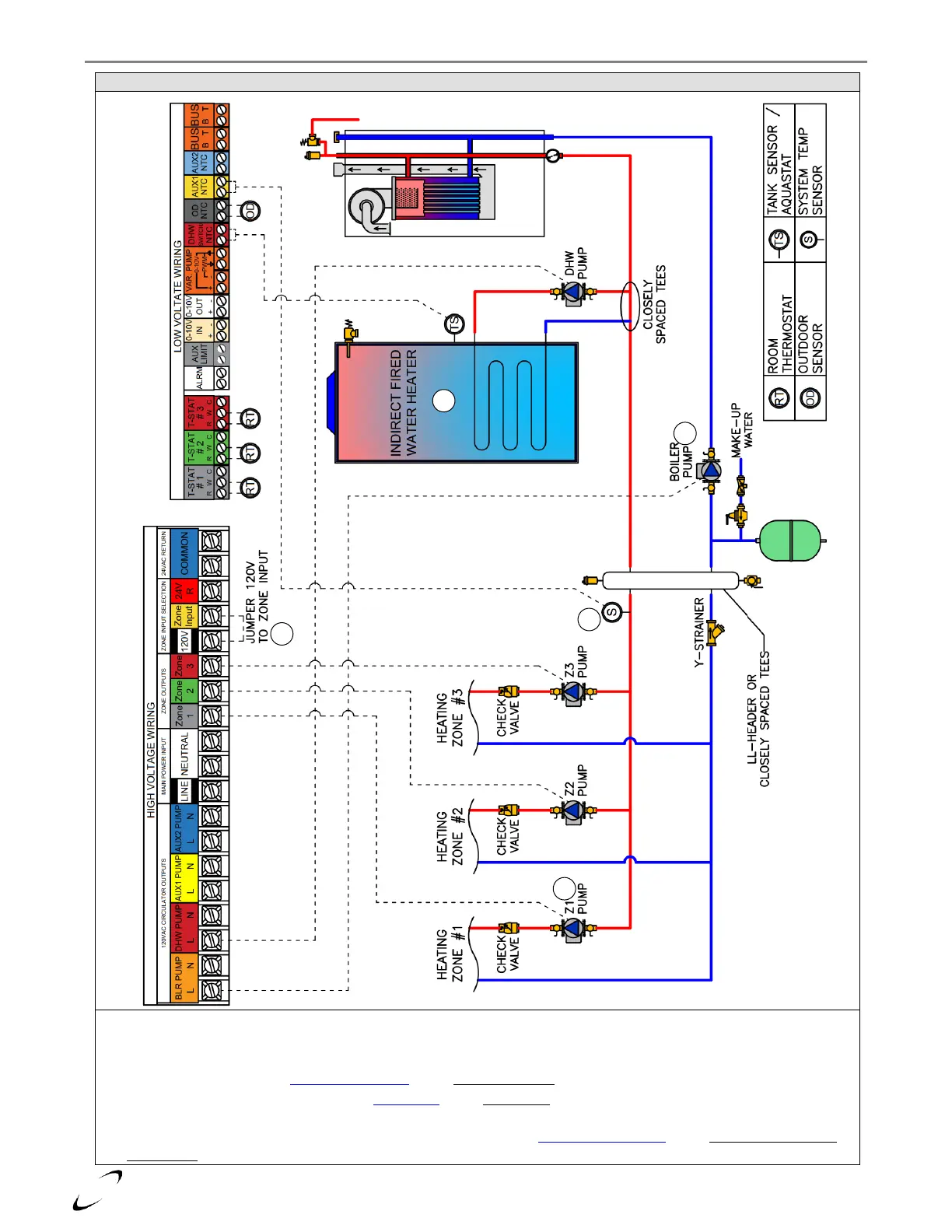
1. For ZONE 1-3 to output 120VAC (like in this example), jumper ZONE INPUT to 120V
2. The BOILER PUMP is responsible for circulating water through the boiler, so size accordingly (see Table 10.3).
3. If using a System Sensor, set Sensor Configuration option Auxiliary Sensor 1 (24.6.1) = System Sensor.
4. If the application uses a System Sensor, set DHW Setup option DHW Mode = Upstream IWH (Tank Sensor or Aquastat);
otherwise it can be set as Downstream IWH (Tank Sensor or Aquastat).
5. To prevent zone pumps from post-circulating during DHW demands, set Pump Control Settings option Zone Outputs Overrun
During DHW (7.2.9) = Off.