Trinity Lx │Installation and Operation Instructions Lx Series
68
Summary and Diagnostics Display – The Trinity Lx controller and Touchscreen display provides detailed
operational and diagnostic information for aid in troubleshooting. When power is applied to the appliance the
initial page displayed is the Summary page. Information presented on the Summary page includes Demand
source, Burner state, status of sensors and pumps, and so forth. Any current Alert or Lockout condition is also
displayed. Accessible from the Summary page are the Diagnostics pages. Refer to the controller manual for more
information.
Lockout and Alert History – The controller maintains a record of the fifteen (15) most recent events for both
Lockouts and Alerts. To display the logs, touch the History button on the Summary page (refer to Section 7.0 in
Appendix A - Controller and Touchscreen Display Instructions). In any situation where malfunction is
suspected, always check the Alerts and Lockouts history. Entries recorded in the history provide useful
information for determining the cause of the malfunction.
Optional Plug In Module (PIM) – The Trinity Lx controller has an optional removable plug in memory module
called a PIM (NTI P/N 83998). The PIM is not supplied with the boiler and must be ordered separately if backup
and restore options are desired. A copy of the non-safety configuration parameters can be stored (backed-up) to
the PIM to be restored at a later date (i.e. if the controller settings are subsequently changed) or copied to another
boiler of the same model. The PIM can be useful to a heating technician who wishes to modify many of the
factory settings and copy those settings to multiple boilers. (Note: the PIM may be inserted and removed from the
controller with power applied). Restore the settings to the new controller with the following procedure:
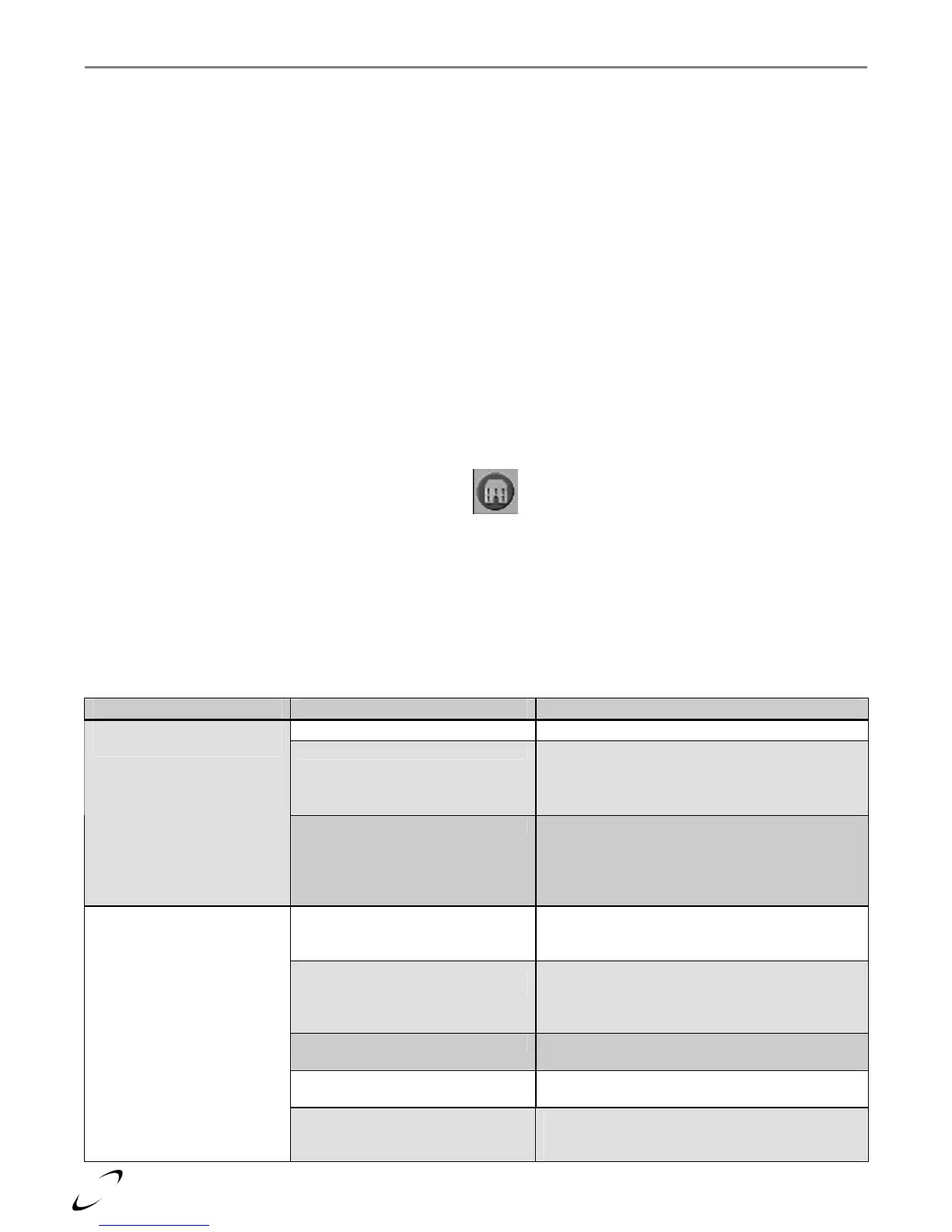
• To display the Summary page, touch the Home icon at the upper left corner of the screen.
• Touch the Configure button at the lower left corner of the Summary page.
• Touch the Display Setup button at the lower right corner of the Configuration page.
• Touch the Program Module button located near the center of the Display Setup page.
• Touch the Login button at the lower right and enter the correct password; “sola”.
• Touch the Restore Parameters button.
• Confirm the restore operation by touching the Yes button.
Table 14-1 Troubleshooting Chart
PROBLEM POSSIBLE CAUSE CORRECTIVE ACTION
Blown 24VAC fuse
Check Fuse
"C" using procedure above.
Faulty 24VAC transformer Check Power LED on controller. Verify 24VAC
to controller by measuring voltage at terminals J8
1 & 2. If no 24VAC detected and Fuse "C" ok,
replace transformer.
Display shows “System
Disconnected” constantly
Faulty controller If 24VAC present at controller terminals J8 1 & 2,
check Power LED on controller. Verify that
connector J8 is securely plugged into the
controller. Recycle power to appliance, if
controller does not operate, replace the controller.
Heat demand satisfied; no call for
heat
Check Demand and Set points via Touchscreen.
Check thermostat and DHW aquastat (if
applicable) setting.
Appliance outlet temperature
exceeded “Off Hysteresis”
Check outlet temperature, setpoint and hysteresis
settings via Touchscreen. By design, if the outlet
temperature exceeds the demand setpoint plus the
Off Hysteresis, the burner shuts down.
Hold or Delay Check Summary page on Touchscreen for
specific cause of hold or delay.
Lockout Check Summary page on Touchscreen for lockout
code.
Burner not operating
Burner switch off Check Summary page, if Demand indicates
“Burner switch off” go to diagnostics burner test
a
e and switch on.