EasyManua.ls Logo

NTI GF 200 User Manual

NTI GF 200
40 pages
To Next Page IconTo Next Page
Page #1 background imageLoading...
Page #1 background image
* Lead Free
Keep this manual near this appliance for future reference
whenever maintenance or service is required.
* The wetted surface of this product contacted by consumable water contains
less than one quarter of one percent (0.25%) of lead by weight.
GF 200 Installation Manual
Combination gas-fired, condensing
instantaneous hot water heater and space heating fan coil
WARNING
This appliance (GF 200) is a combination gas-fired, condensing, instantaneous hot water heater
and space heating fan coil. The water heater is a CSA-certified product in its own right and, as
such, must be installed according to its installation and operation manuals (supplied).
This manual provides installation instructions for the GF 200, but defers to the water heaters
manual(s) where appropriate. Throughout, in any conflict between instructions from this manual
and those from the water heaters, the latter are assumed to be correct. When reading the water
heater’s manual, only sections pertaining to the NPE-240A model may apply.
If the information in these instructions is not followed exactly, a fire or explosion may result,
causing property damage, personal injury or death.
Do not store or use gasoline or other flammable vapors and liquids in the vicinity of this or any
other appliance.
What to do if you smell gas
Do not try to light any appliance.
Do not touch any electrical switch; do not use any phone in your building.
Immediately call your gas supplier from a neighbor’s phone. Follow the gas suppliers instructions.
If you cannot reach your gas supplier, call the fire department.
Installation and service must be performed by a qualified installer, service agency or the gas supplier.
The installation must conform with local codes or, in the absence of local codes, the National Fuel
Gas Code, ANSIZ223.1/NFPA 54 and/or CSA B149.1, Natural Gas and Propane Installation Code.
When applicable, the installation must conform with the Manufactured Home Construction and
Safety Standard, Title 24 CFR, Part 3280 and/or CAN/CSA Z240 MH Series, Mobile Homes.
Question and Answer IconNeed help?

Do you have a question about the NTI GF 200 and is the answer not in the manual?

NTI GF 200 Specifications

General IconGeneral
BrandNTI
ModelGF 200
CategoryWater Heater
LanguageEnglish

Summary

GF 200 Installation Manual

Safety Warnings and Gas Leak Procedures

Key safety warnings and steps to take if a gas leak is detected.

Important Information

Safety Symbols and General Precautions

Explanation of safety symbols and general safety guidelines for operation.

Additional Safety Guidelines

Further safety precautions regarding flammable materials, electrical shock, and operation.

Appliance Description

Included Items and Optional Accessories

Details on what is included with the appliance and available optional accessories.

Technical Specifications Table

Specifications including heat capacity, flow rate, dimensions, and electrical ratings.

Front Panel Operation and Display

Explanation of the front panel controls, buttons, and display indicators.

Appliance Component Identification

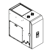
Diagram identifying the major internal and external components of the appliance.

Physical Dimensions and Connection Layout

Diagrams showing the appliance's dimensions and port locations.

Understanding the Rating Plate Details

Guidance on interpreting the appliance's rating plate for installation requirements.

Installation Guide

Choosing a Suitable Installation Location

Factors to consider for selecting the best location for appliance installation.

Installation Clearance Requirements

Mandatory clearances around the appliance for safety and service access.

Gas Supply Installation

Gas Supply Connection Procedure

Step-by-step instructions for connecting the natural or propane gas supply.

Gas Piping Configuration and Examples

Recommended piping configurations and examples for gas supply lines.

Natural Gas Pipe Sizing Tables

Reference tables for determining appropriate natural gas pipe sizes based on length and capacity.

Propane Gas Pipe Sizing Tables

Reference tables for determining appropriate propane gas pipe sizes based on length and capacity.

Water Supply Installation

Plumbing Connections and Guidelines

Details on plumbing connection kits and general guidelines for water supply installation.

Typical Plumbing Layout

Diagram illustrating a typical near-appliance plumbing layout for connections.

Pressure Relief Valve Installation

Instructions for installing the required safety pressure relief valve.

Configuring Recirculation Mode

Setting the DIP switches to enable or disable the pre-heat recirculation feature.

Condensate Drain Setup

Condensate Disposal Options

Overview of different methods for disposing of appliance condensate.

Condensate Drain Connection Procedure

Steps for connecting the condensate drain line to the appliance.

Appliance Venting

Adjusting Space Heating Settings

Procedure to limit the maximum space heating setpoint and implications for venting.

Electrical Connection

Power Supply Wiring Guidelines

Instructions and warnings for connecting the 110-120V AC power supply.

DIP Switch Settings

Interface and Front Panel DIP Switch Functions

Detailed description of DIP switch functions for configuration.

Ducting Installation

Supply and Return Air Ducting

Instructions for connecting supply and return air ductwork to the appliance.

Appliance Configuration

Setting Air Flow Rates

Procedure for configuring the cooling air flow rates using the appliance's controls.

Setting DHW Temperature

How to adjust the Domestic Hot Water (DHW) setpoint via the front panel.

Field Wiring Connections

Connecting flow switch, thermostat, and other field wiring to the appliance.

Appendices

Blower Performance Data

Graph and table detailing the blower's performance characteristics.

Appliance Wiring Diagram

Schematic illustrating the electrical wiring of the GF 200 and its components.

Control Logic Ladder Diagram

Diagram representing the control logic and signal flow within the appliance.

Case Assembly Diagrams and Parts

Exploded view and part numbers for the appliance's case assembly.

Case Assembly Parts List (Continued)

Continuation of the parts list for the case assembly.

Waterway Assembly Diagrams and Parts

Exploded view and part numbers for the appliance's waterway components.

Waterway Assembly Parts List (Continued)

Continuation of the parts list for the waterway assembly.

Installation Verification Checklist

A checklist to confirm all installation steps have been completed correctly.

Troubleshooting Procedures

Troubleshooting: Circulation Pump Error (E.438)

Steps to diagnose and resolve circulation pump errors due to air-lock or sensor issues.

Troubleshooting: Fan Not Running

Steps to diagnose and resolve issues where the circulating fan is not operating.

Service and Support

Getting Service and Technical Assistance

Information on how to obtain service, warranty, and technical support.

Related product manuals