3. Determine which side of the appliance the inlet
and outlet water connections will be made on.
A) Left side connections
B) Right side connections
C) Both - One on each side
NOTE: Typically both water connections are
installed on the opposite side of the return air duct
to allow for air lter & maintenence clearances.
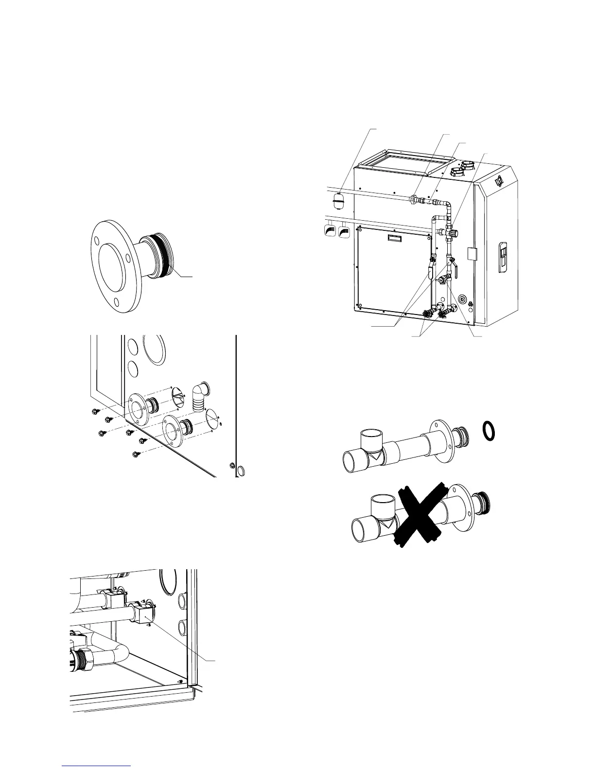
4. Install the plug adapters opposite the inlet and
outlet connections.
Slide each plug through the hole in the cabinet and
into the corresponding pipe; secure with (3) screws
(PN: 82998) and (1) pipe clip (PN: 85371).
MUST ATTACH O-RING BEFORE SECURING.
ATTACH O-RING
PN: 85369
ATTACH PIPE CLIPS
PN: 85371
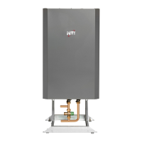
COLD
SUPPLY
HOT
SUPPLY
UNION
FLOW SWITCH
TEMPERING VALVE
SHUT OFF
VALVES
DRAINS
The following is a typical near-appliance plumbing
layout for connections on the same side.
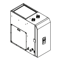
NOTE: Do not block service door
5. Solder pipe and pipe ttings onto the open
brass connection adapter (PN: 85372) prior to
securing to the cabinet and internal plumbing.
IMPORTANT: Do not solder to brass adapter with
O-ring installed.
6. Install the ow switch on the inlet piping up-
stream of the tempering valve as shown above.
Connect the ow switch cable to terminals 1 and 2
“FLOW SWITCH” on the eld wiring barrier strip.
7. A tempering valve must be installed on the
hot water outlet to prevent scalding. See drawing
above.
SERVICE DOOR
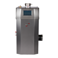
PRESSURE
RELIEF VALVE
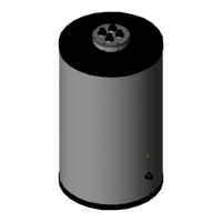
EXPANSION TANK
17
 Loading...