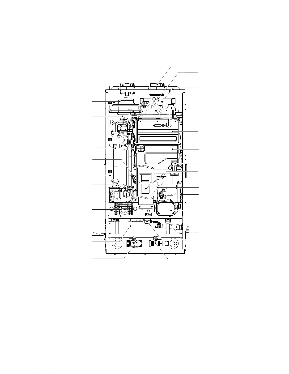
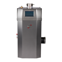
2.5 Components
The following diagram shows the key components of the appliance. Component assembly diagrams and
particular parts lists are included in the Appendixes.
Intake Air Duct
Exhaust Duct
Exhaust Limit Temperature Sensor
Exhaust Body
Ignition Transformer
Burner
Primary Heat Exchanger
Secondary Heat Exchanger
Flow Sensor
Condensate Trap
Front Panel
PCB Box
Water Adjustment Valve
Water Inlet Filter
Condensate Drain
Condensate Drain Lid
Combustion Fan Motor
Dual Venturi
Gas Pipe
APS (Air Pressure Sensor)
Buer Tank
Circulation Pump
Gas Valve
Gas Inlet Fitting
DHW Inlet Fitting
Field Wiring Panel
Recirculation Inlet Fitting
GF 200
DHW Supply Fitting
3-Way Valve
Service Valve
7
Central Heating System Controller