3.7 Connecting the Power Supply
WARNING
Improperly connecting the power supply can
result in electrical shock and electrocution.
Follow all applicable electrical codes of the local
authority having jurisdiction. In the absence of
such requirements, follow the latest edition of the
National Electrical Code (NFPA 70) in the USA or the
latest edition of CSA C22.1 Canadian Electrical Code
Part 1 in Canada. Connecting the power supply
should be performed only by a licensed professional.
When connecting the power supply, follow these
guidelines:
●
Do not connect the electric supply until all
plumbing and gas piping is complete and the
appliance has been lled with water.
●
Do not connect the appliance to a 220-240 V
AC power supply. Doing so will damage the
appliance and void the warranty.
●
This appliance must be wired directly. It is
recommended that a power switch be installed
between the breaker and the appliance to
facilitate end-user maintenance and servicing.
●
Connect the appliance to a 110-120 V AC circuit
at 60 Hz, with a minimum circuit ampacity (MCA)
of 15 A, and a maximum circuit breaker size of 20
A, as per the rating plate.
●
Ensure that the appliance is electrically grounded
via the GND circuit on the barrier strip. Do not
attach the ground wire to either the gas or the
water piping as plastic pipe or dielectric unions
may prevent proper grounding.
●
If there is a power failure in cold weather areas,
the freeze prevention system in the appliance
will not operate and may result in freezing of
the heat exchanger and or coil. In cold weather
areas where power failures are common, you
must completely drain the appliance to prevent
damage if the power will be o for any extended
period of time. A battery back-up (available at
most computer retailers) may be used to supply
hot water during periods of power outages.
Damage caused by freezing is not covered under
warranty.
3.8 Setting the DIP Switches
The appliance has two installer-serviceable DIP
switch locations: on the front panel, and on the
interface board, mounted on the frame of the PCB.
3.8.1 Interface Board DIP Switches (H2Air)
The four DIP switches on the interface board
congure the settings governing central heating
operation. These congurations are set at the
factory (OFF ON OFF OFF) and should not be
changed.
However, should absolute DHW priority be desired,
such that any DHW demand disables any central
heating operation for the duration of the demand,
DIP switch #2 may be set to OFF.
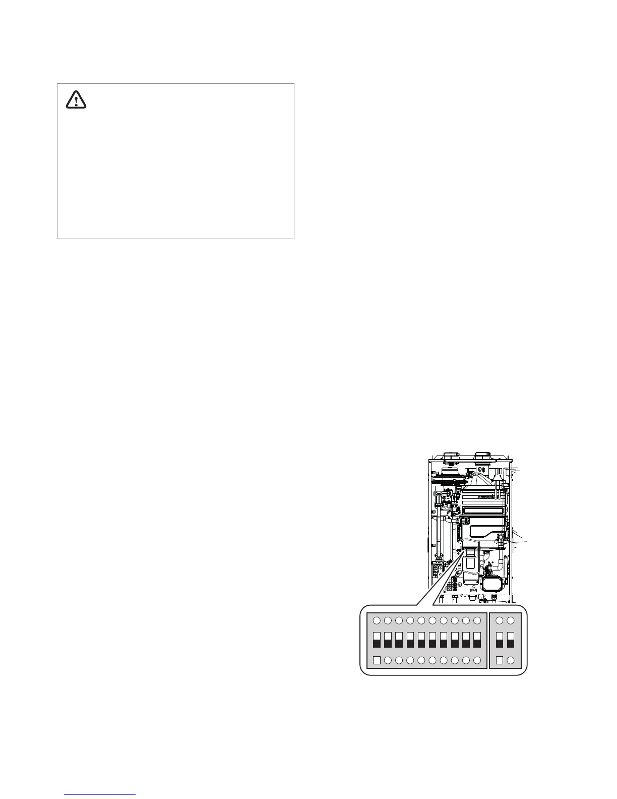
3.8.2 Front Panel DIP Switches
The two sets of DIP switches on the front panel
congure the appliance pump & recirculation,
display, well pump, storage tank & solar system,
lime alarm, high altitude, cascade venting and gas
type settings. Some of these congurations are
set at the factory and should not be changed. The
following tables describe the functions of the DIP
switches and their settings:
1 2 3 4 5 6 7 8 9 10
ON ON
22
 Loading...