& & $' &#"
! ! !
+ + + +
+ + + *
+ + * +
+ + * *
+ * + +
+ * + *
+ * * +
+ * * *
* + + +
* + + *
* + * +
* + * *
* * + +
* * + *
* * * +
* * * *
$ #(%&&"%
%
" *) +
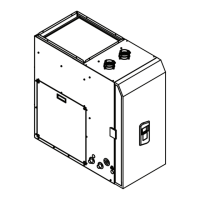
3.10 Conguring the appliance
The appliance is designed to operate with
second-stage (Y2) cooling air ow rates between
700 and 1450 CFM. First-stage (Y1) cooling and
circulation air ow rates are set to 70% and 50% of
second-stage (Y2) rates, respectively. Depending
on cooling capacity, climatic conditions, and owner
preference, one may choose any Y2 value between
700 and 1450, in increments of 50 CFM (see table
below). Once a value is selected (by following the
steps in 3.10.1), it will remain in solid-state memory.
The default setting is ‘maximum’ (all 4 LEDs illumi-
nated).
The following rates apply at all operating points
within the prescribed external static pressure range:
0 - 0.8” w.c.
25
3.10.1 Setting air ow rates:
1. Remove the front cover from the appliance
2. Connect the appliance to mains power and ip
the main power switch ON
3. Using the soft-touch button on the Front Panel,
turn the water heater OFF
4. Remove the protective cover from the controller
enclosure (4 Phillips head screws).
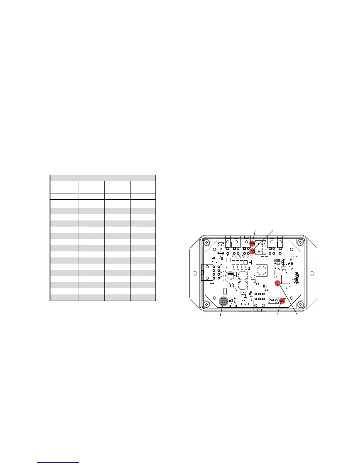
5. Locate the push-button in the lower left corner of
the controller enclosure (see gure below).
6. Locate the 4 numbered LEDs (boxed below) that
will indicate the air ow programming setting.
a. Note the 3 unlabeled LEDs (circled below)
which will remain lit or ashing throughout
this process. These 3 are not part of the
programming procedure.
b. LED #4 (HB) will ash steadily during
normal operation.
7. Press and hold the Bootloader button for 3
seconds (LED #4 will stop ashing for these seconds)
then release it. This activates programming mode,
where the numbered LEDs will identify which mode
is currently programmed.
8. Each subsequent press increases the
second-stage (Y2) cooling air ow rate by 50 CFM, as
per the table above. Once all 4 LEDs are lit
(Y2 = 1450 cfm), the next press will loop back to the
beginning (Y2 = 700 cfm).
9. Conrm the setting using the 4 LEDs (shown in
the gure below and the table above).
10. Once the desired setting is selected, wait 10
seconds. The LEDs will return to their former state,
and the values will be saved as the controller exits
programming mode.
LED #1LED #2
LED #3 LED #4PUSH BUTTON
 Loading...