RECIRCULATION MODE
This appliance comes factory set for pre-heat
recirculation.
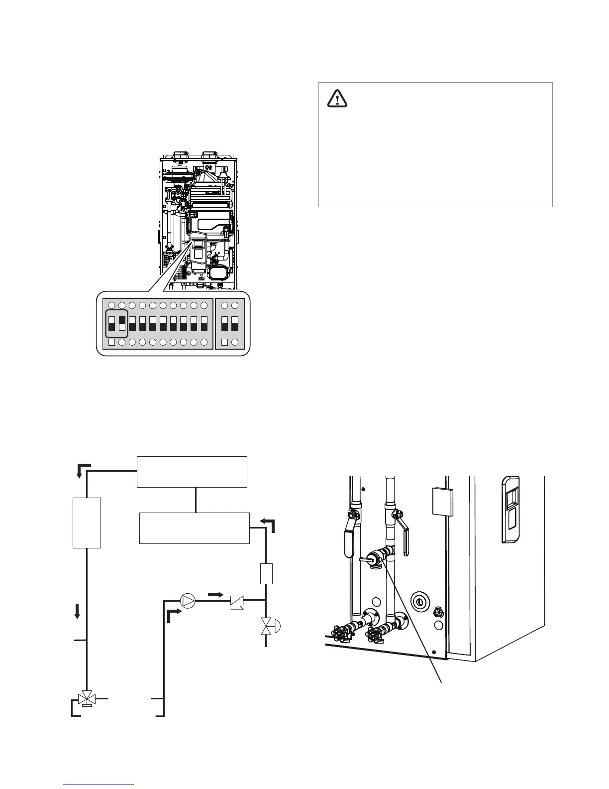
1. The Front Panel DIP switches (set of ten) are
factory set to: 1—OFF; 2—ON.
1 2 3 4 5 6 7 8 9 10
ON ON
2. To disable pre-heat recirculation, set DIP switch
#2 to the o (down) position.
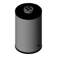
The following diagram shows the recirculation ow
for pre-heating:
Primary Heat Exchanger
Secondary Heat Exchanger
Flow
Sensor
Domestic
Water
Supply
Bypass
Pump
Check
Valve
Water
Adjustment
Valve
Buer
Tank
Hot
Supply
Space Heating Loop
18
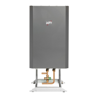
3.4.2 Connecting a Pressure Relief Valve
WARNING
Improper installation of the pressure relief valve
may result in property damage, personal injury,
or death. Follow all instructions and guidelines
when installing the pressure relief valve. The
valve should be installed only by a licensed
professional.
To complete the installation of the appliance, you
must install an approved
3
/
4
in, maximum 150
PSI pressure relief valve on the hot water outlet.
The appliance's water heater has a built-in high
temperature shut o switch, so install a “pressure
only“ relief valve. This valve is not supplied, but is
required. The following examples are approved for
use with the appliance:
●
Wilkins P-1000A (Zurn Industries)
●
Conbraco 17-402-04
●
Watts Industries 3L(M7)
●
Cash Acme FWL-2,
3
/
4
in
The pressure relief valve should be placed as close
to the hot water outlet as possible. No other valve
should be placed between the pressure relief valve
and the appliance.
Pressure
Relief Valve