Trinity Lx │Installation and Operation Instructions Lx Series
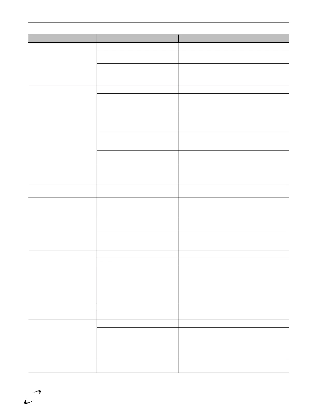
Table 17-1 Troubleshooting Chart
Lockout 122 – Lightoff rate
proving failed
See “Blower not operating” below.
Missing or incorrect blower
feedback signal
See “Blower operating at high speed while burner
is off” below.
Alert 128 - Modulation rate
was limited due to IAS was
open (Air switch open while
burner firing)
Check for blockage of the exhaust vent.
Check for blockage of the air inlet.
Lockout 173 - Pilot relay
feedback incorrect
Lockout 174 – Safety relay
feedback incorrect
External Electrical Noise
Look for sources of electrical noise, i.e. a large
motor or multiple pieces of equipment starting at
the same time.
Failing Limit Switch in ILK circuit
Check operation of internal LWCO, and/or
external limit (i.e. devise connected between “R”
and “LIM”); replace as necessary
Hardware failure of Sola controller
Reset power, If problem persists replace Sola
controller.
Alert 206 – Lead Lag header
temperature was invalid
System Sensor not connected
If desired, install System Sensor and wire to
sensor input connections “SYSTEM” and
“SENSOR COM”. Otherwise ignore Alert 206
Alert 233 – Lead Lag outdoor
temperature was invalid
Alert 248 – CH outdoor
temperature was invalid
Outdoor sensor not connected
The Trinity Lx is factory set with Outdoor Reset
enabled. Connect outdoor sensor or disable
Outdoor Reset.
Check wiring of outdoor sensor. Wires should
connect to Low Voltage barrier terminals 11 & 12.
Check sensor. Should be free of ice and snow.
Check resistance of sensor and compare to
thermistor resistance chart, see Table 17-2.
Alert 311 – Run was
terminated due to interrupted
air flow switch was off
Check for blockage of the exhaust vent.
Check for blockage of the air inlet.
Disconnected, damaged or blocked
tubing
Inspect the clear vinyl tubing connecting the air
switch + and – ports to the air metering elbow.
Condensation or other foreign matter may be
obstructing the tubing, preventing the switch from
sensing differential pressure caused by air flow
through the metering elbow.
Incorrect air switch setting
Contact NTI technical support.
Inoperative CH and/or DHW
pump
If Fuse “B” not blown, and controller is operating,
navigate to pump diagnostic on display. Manually
switch pump on, check for 120VAC at pump
connection terminal on line voltage barrier strip. If
120VAC not detected, replace controller.
If 120VAC supplied to pump, and pump does not
operate, replace pump.