Rev. December 19, 2008 Page 9 of 19
For residential applications you should have a minimum ventilation capacity of 10 cfm (5 L/s) per room.
The chart that accompanies the flow grid calibrates pressure readings to airflow.
Refer to ASHRAE Standard 62 for acceptable ventilation rates in commercial buildings.
Calculating TVC (Total ventilation Capacity) for Residential Applications
• 20 cfm for the master bedroom
• 20 cfm for an unfinished basement
• 10 cfm for each other room in the house
Add these together to arrive at your TVC.
This method is called the “Room Count Method” and is part of CSA F326 (Residential Mechanical
Ventilation Systems). 0.3 air change per hour is no longer used.
Air meter available from Nu-Air wholesalers. (Part #100460)
Balance the HRV in less than five minutes.
3. CONTROLS
Your machine is equipped for remote controls. Options include humidity sensing, off-on control,
intermittent & continuous modes, as well as high speed control from the dehumidistat or timer(s). You
can also interlock the furnace blower to the HRV. Various means of controlling the system are described
below.
3.1. Features:
• Powerful transformer – up to six (6) WIN-20 Timers can be connected in
parallel
• Field selectable defrost cycle for northern applications
• Self-resetting fuse to protect the board against mis-wiring
• Variable low speed control – HRV low speed can be adjusted between a
minimum of 40% and a maximum of 70% of high speed. See below for
explanation.
• Optional setting for 220V/50Hz geographic areas
The following sections outline the features and explain the board in greater
detail. In most applications, the factory settings for speed control, defrost, electrical service and
fan/motor type will never need to be changed. A qualified technician must do any service work done
within the electrical panel of the HRV.
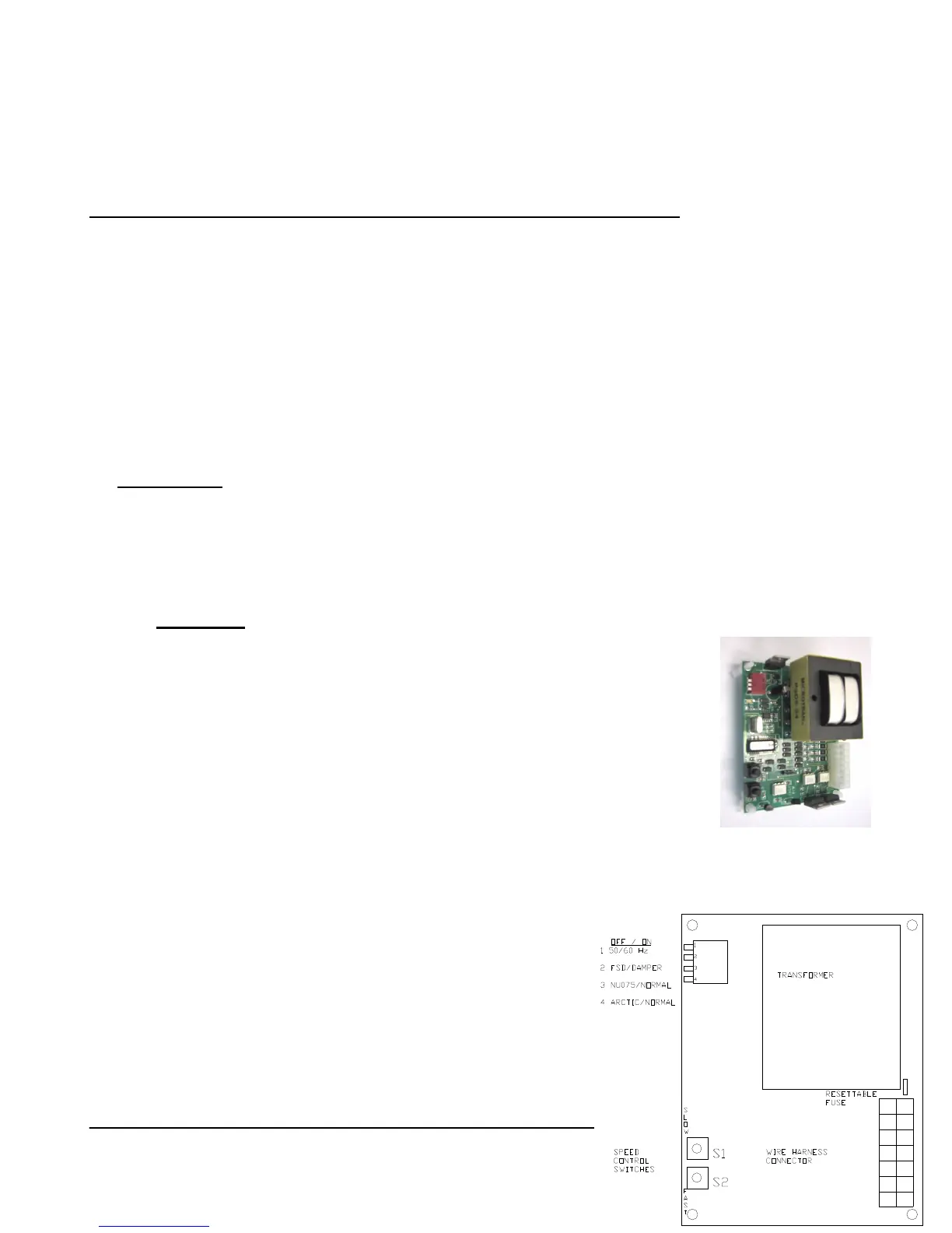
DIP Switches:
An array of four (4) two position switches are located at the top
left corner of the board. The "On" position for each switch is
labeled and corresponds to down (i.e. towards the board surface).
The "Off" position is up or away from the board surface. The
switches are labeled 1-4 and their settings determine the
following conditions.
 Loading...