407 reflective beam line-type smoke detector
Installation and Service Manual
6
32-0061-r04_2020-10
© 2019, 2020 Ambest Electronics (Ningbo) Co Ltd. All rights reserved.
All specifications and other information shown were current at the date of publication and subject to change without notice.
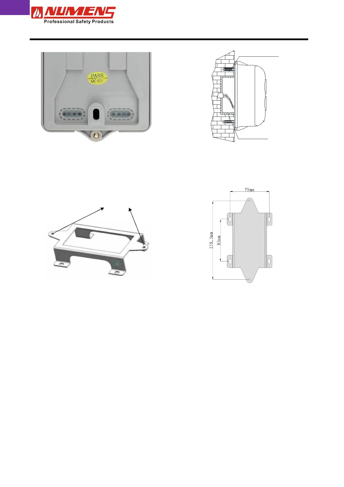
Plastic Expansion Bolt
Embedded Box
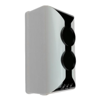
Fig. 5 – Transceiver base cable entry holes
Fig. 6 – Surface mounted transceiver
2.6.2. Mounting Bracket
The mounting bracket is used where the cabling to the transceiver is installed on the surface of the wall. The
mounting bracket provides space for the wiring to enter the rear of the transceiver base.
Transceiver mounting points
Fig. 7a – Mounting bracket
Fig. 7b – Mounting bracket drill template
To install the mounting bracket on the surface of the wall, complete the following steps.
1) Mark the mounting bracket hole locations as shown in Fig. 7b.
2) Drill four holes and install 6 mm wall plugs.
3) Fix the mounting bracket to the wall using four ST4 x 30 screws.
To install the transceiver complete the following steps.
1) Separate the transceiver cover from the body by removing the M4 screw located at top of the transceiver
(see Fig. 1).
2) Push the conductors through the transceiver entry holes at the bottom of the base.
3) Screw the base to the bracket using the M4 x 10 screws and flat washers.