407 reflective beam line-type smoke detector
Installation and Service Manual
5
32-0061-r04_2020-10
© 2019, 2020 Ambest Electronics (Ningbo) Co Ltd. All rights reserved.
All specifications and other information shown were current at the date of publication and subject to change without notice.
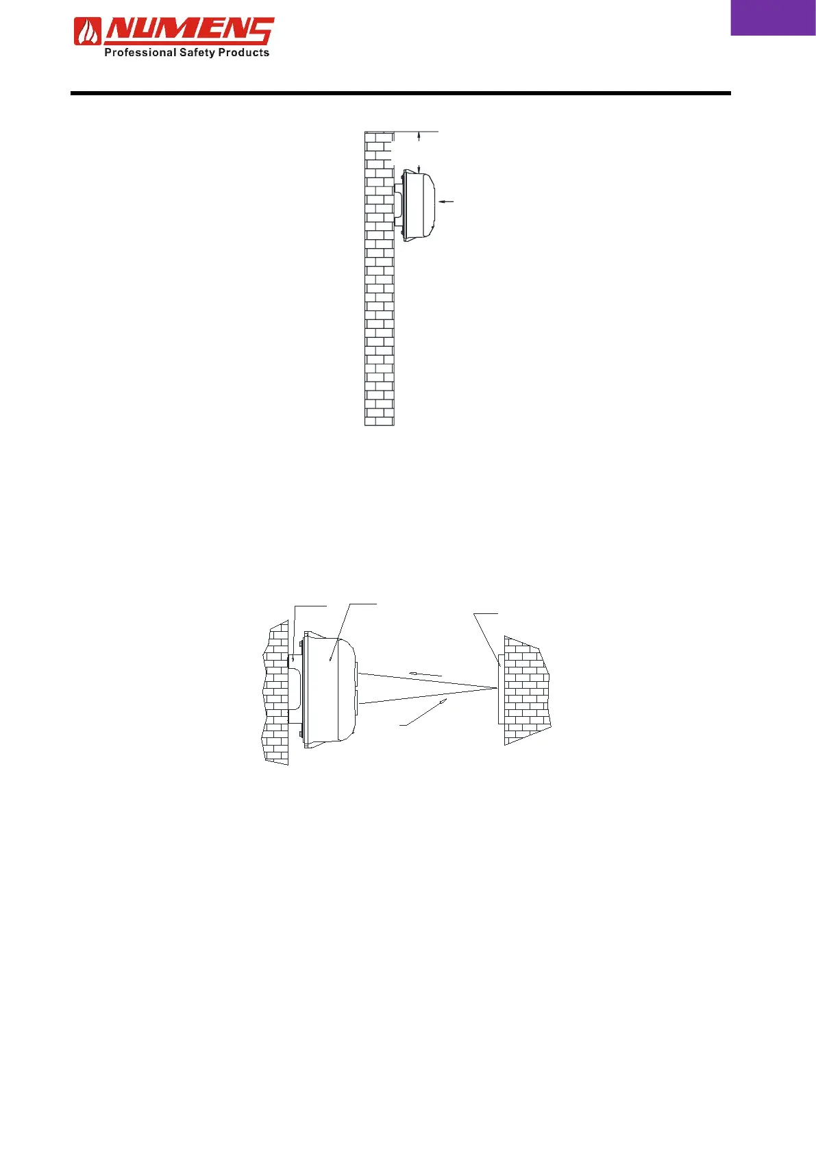
Fig. 3 – Transceiver mounting height
2.5. Transceiver and Reflector Orientation
The transceiver and the reflector must be mounted on the same horizontal plane and are parallel to each
other. Some alignment adjustment is available, but if the received beam is reflected such that it is no longer
parallel to the transmitted beam, then the performance of the detector will be negatively impacted.
Ensure the optical pathway is directly to and from the reflector, and is not received by the transceiver from
other reflective surfaces.
Mounting
Bracket
Detector
Reflector
Fig. 4 – Transceiver and reflector orientation
2.6. Transceiver
2.6.1. Surface Mounting
Where cabling is embedded into the wall, the transceiver may be mounted directly on the wall surface. To
install the transceiver complete the following steps.
1) Separate the transceiver cover from the body by removing the M4 screw located at top of the transceiver
(see Fig. 1).
2) Align the base over the cable cavity and mark the positions of the two base mounting holes.
3) Drill two holes and install 6 mm wall plugs.
4) Push the conductors through the transceiver entry holes at the bottom of the base.
5) Screw the base to the bracket using the M4 x 10 screws and flat washers.