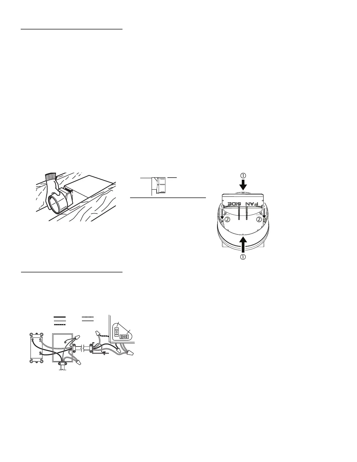
CONNECT THE WIRING
1.
Wire unit following diagram. Run electrical cable as direct as possible to unit. Do not allow cable to touch sides or top of unit after instal-lation is
complete.
SWITCH BOX
FAN
DUAL CONTROL
(purchase separately)
WHITE
BLACK
RED
GROUND
(bare)
WIRING
PLATE
120 VAC
BLUE
BLACK
(FAN)
RECEPTACLE
(LIGHT/SPEAKER)
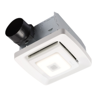
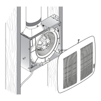
INSTALL THE DUCTWORK
NOTE: The duct connector has a counter-balanced damper flap. The flap will be “open” approx. 1” when duct connector is attached to housing. This design
permits insulation to be in direct contact with fan/light housing per UL (Underwriters Laboratories) standards. The slightest backdraft, however, will close the damper
flap, preventing air from entering unit or finished space.
1. Snap the damper/duct connector onto housing.
Make sure that tabs on the connector lock into slots in housing. Top of damper/duct connector should be flush with top of housing.
NOTE: Make sure damper flap is in place inside of
duct connector. If it is not:
Squeeze top and bottom of connector to
snap flap back into place.
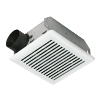
2. Connect 4” round duct to damper/duct connector
and extend duct to outside through a roof or wall cap. Check damper to make sure that it opens freely. Tape all duct connections to make them secure
and air tight.
FLUSH