Do you have a question about the NUVE NB 9 and is the answer not in the manual?
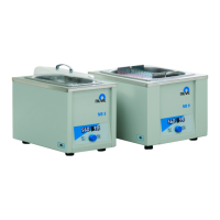
Provides a detailed comparison of NB 5, NB 9, and NB 20 models regarding temperature, power, dimensions, and more.
Emphasizes using the instrument only for its intended purpose, by trained staff, with original parts and proper grounding.
Advises on sample temperature, sealed containers, liquid expansion, and material compatibility for safe heating.
Details the required voltage, frequency, and grounding for the instrument's power connection.
Details the operational status displays (temperature, time) and the functions of control buttons and indicators.
Outlines essential pre-operation tasks: grounding, power on, system activation check, and control panel familiarization.
Instructs on filling the water bath tank with distilled water to the maximum line and safety precautions.
Details specific operator menu parameters like Recording Period, Timer Set Band, Buzzer settings, and Date/Time configuration.
Lists essential checks to perform if the device fails to operate, such as power switch, fuses, and plug.
Explains common error codes (Er1-Er4, EoF) displayed on the unit and their potential causes.
| Brand | NUVE |
|---|---|
| Model | NB 9 |
| Category | Laboratory Equipment |
| Language | English |