EN
Installation and repairs must be
made by a qualied bicycle
mechanic.
This manual assumes a level of
knowledge and skill consistent
with that of an experienced
bicycle assembler or bicycle
mechanic.
2. ASSEMBLY OF COMPONENTS
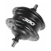
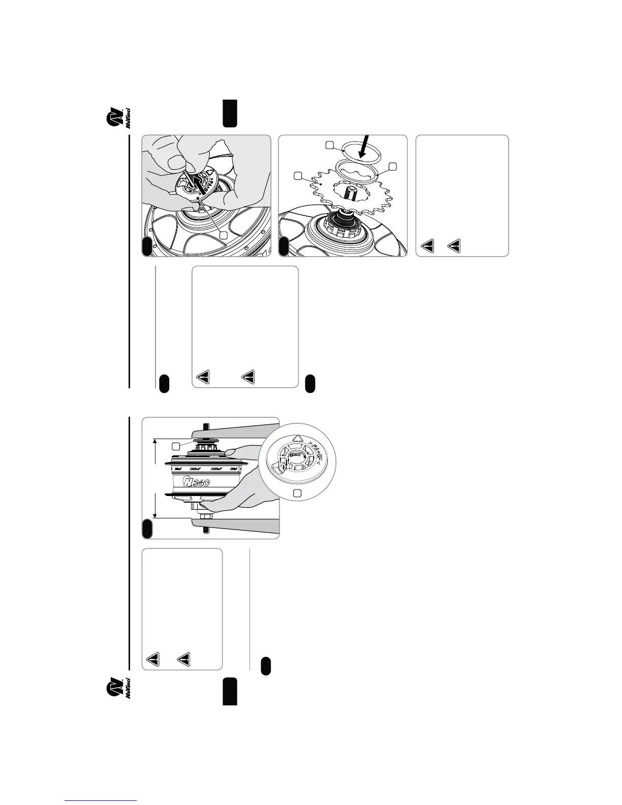
Installing the Sprocket
Remove the anti-shift
retainer (1) by pulling rmly away
from the NuVinci CVP.
Install a standard 9-spline,
3/32 inch (2.3mm) sprocket (2),
followed by the supplied sprocket
spacer (3, if required), and secure
with the sprocket snap ring (4).
fThe sprocket spacer is intended
for sprockets that are 3/32
inch (2.3mm) thick at the inner
diameter. If the inner diameter
is 0.17- 0.18 inch (4.3-4.5mm)
thick, the spacer should not be
used.
fThe N360 is compatible with
16 to 22 tooth sprockets.
fInstall the sprocket for a
chainline closest to the CVP.
If hub interface is not installed
immediately following the
sprocket, replace the anti-shift
retainer (1).
The NuVinci N360 is incompat-
ible with 1/8 inch (3.18mm)
single-speed chains and sprock-
ets. Use 3/32 inch (2.3mm)
chains and sprockets only.
Use of incompatible chains can
result in interference with the
hub interface and damage to
N360 components and may
result in a dangerous condition
for the rider.
If the sprocket is asymmetric,
incorrect installation can result
in interference with the hub
interface and damage to N360
components and may result in
a dangerous condition for the
rider.
See Section 6 “TECHNICAL
DATA” for Sprocket Ratio
requirements.
2. ASSEMBLY OF COMPONENTS
3
4
EN
2.1
2.2
2.3
1
2
3
4
2.2
2.3
1
135mm
2.1
1
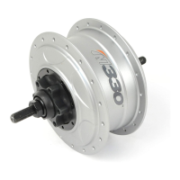
Wheel Building
The anti-shift retainer (1)
provides 135mm spacing, and
should remain on the CVP during
lacing and wheelbuilding.
fMaximum spoke diameter is
#13 / 2.34mm.
fMinimum spoke diameter is
#14 / 2.00mm.
Suggested lacing is a 2-cross
pattern for 26-inch and 700c
wheels.
fUse a 2-cross pattern only if
the rim allows the nipples to
be effectively in-line with the
spokes.
For 24-inch or smaller wheels a
1-cross pattern is suggested.
Radial lacing is not recommended.
 Loading...