EN
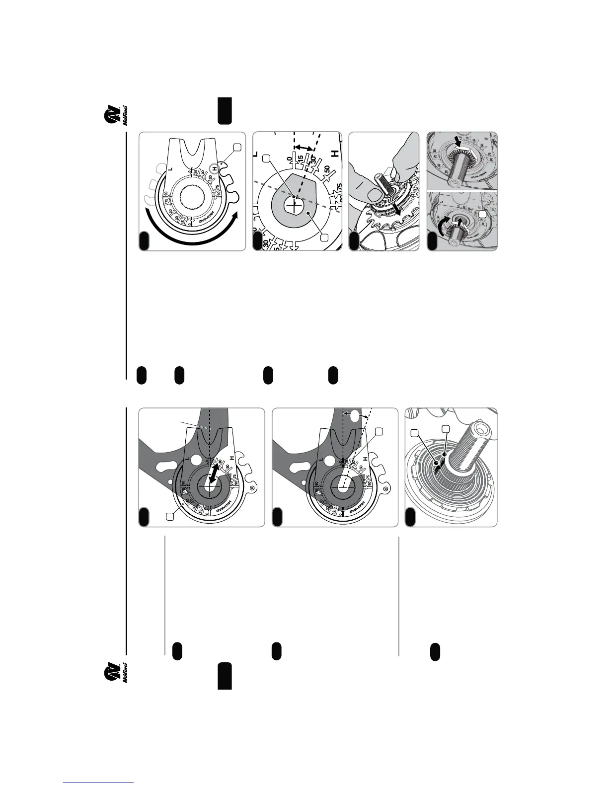
Hub Interface Orientation
and Installation Angle
Use the uninstalled hub
interface (1) to determine the
desired orientation.
fTypical orientation is forward,
parallel to the chain stay or
seat stay cable routing.
fMove the hub interface along
the dropout to ensure clearance
at different axle positions.
With the hub interface
oriented correctly inside the right
dropout, the installation angle (2)
is the indicated angle of the drop-
out (20 degrees in this example).
fUse the markings on the hub
interface to determine your
approximate installation angle.
Installation Angle:__________
2. ASSEMBLY OF COMPONENTS
5
Prior to installation, set the hub
interface to the full overdrive (H)
position (4).
Suspend the hub interface
over the right hand axle, and
align the axle ats (5) with the
installation angle from Step 2.5.
fAlternatively, a no-turn
washer (6) can be installed
over the hub interface to align
the installation angle.
When the installation angle is
aligned, ensure the hub interface
is set to full overdrive (H) and seat
the hub interface fully onto the shift
driver and the spline nut until it is
ush with the spline nut, as shown.
Thread the RH Nut (7),
serrations facing outward, onto
the axle and tighten to 10-15 Nm
(7-11 ft-lbs).
Install the rear wheel per Section 3.
2. ASSEMBLY OF COMPONENTS
6
2.4
2.5
2.7
2.8
2.9
2.10
Installing the Hub Interface
Remove the anti-shift retainer, if
installed (reference Step 2.2).
Ensure that markings between
the splined nut (2) and the shift
driver (3) are aligned. If not,
refer to Step 5.6.
2.6
1
2
0º
2.4
2.5
20º
2
3
2.6
4
2.7
6
5
20º
2.8
2.9
7
2.10
EN
 Loading...