10 | nVent.com
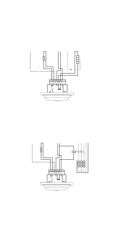
3.3 CONNECTION OF THE THERMOSTAT TO
THE POWER SUPPLY
The thermostat must be connected to 230VAC
according to the circuit diagrams (Figure 6).
Direct connection – e.g. single heating circuit
Connection via contactor – e.g. 3 heating circuits
Pilot wire
signal
(France)
Power supply
230 VAC
Floor
sensor
HEAT
L
N
10K
NTC
PE
SENSOR
N
L
N
L
L
N
PE
PE
FP
Heating cable
230 VAC
Max.13A
10K
NTC
K1
A2
A1
1 3 5
2 4 6
L L L
PE
N N N
L1 L2 L3 N PE
HEAT
SENSOR
N
L
N
L
FP
Pilot wire
signal
(France)
Power supply
230 VAC
Floor
sensor
Power supply to
heating cables
K1: contacter
with integrated
suppression
device
Do not use contactor without interference filter.
Figure 6
If you connect multiple heating cables, you must
use a contactor (Normally Open) with integrated
suppression device (Figure 7).
Direct connection – e.g. single heating circuit
Connection via contactor – e.g. 3 heating circuits
Pilot wire
signal
(France)
Power supply
230 VAC
Floor
sensor
HEAT
L
N
10K
NTC
PE
SENSOR
N
L
N
L
L
N
PE
PE
FP
Heating cable
230 VAC
Max.13A
10K
NTC
K1
A2
A1
1 3 5
2 4 6
L L L
PE
N N N
L
N
L1 L2 L3 N PE
HEAT
SENSOR
N
L
N
L
FP
Pilot wire
signal
(France)
Power supply
230 VAC
Floor
sensor
Power supply to
heating cables
K1: contacter
with integrated
suppression
device
Do not use contactor without interference filter.
Figure 7
 Loading...