•
•
•
•
•
•
•
•
•
•
•
•
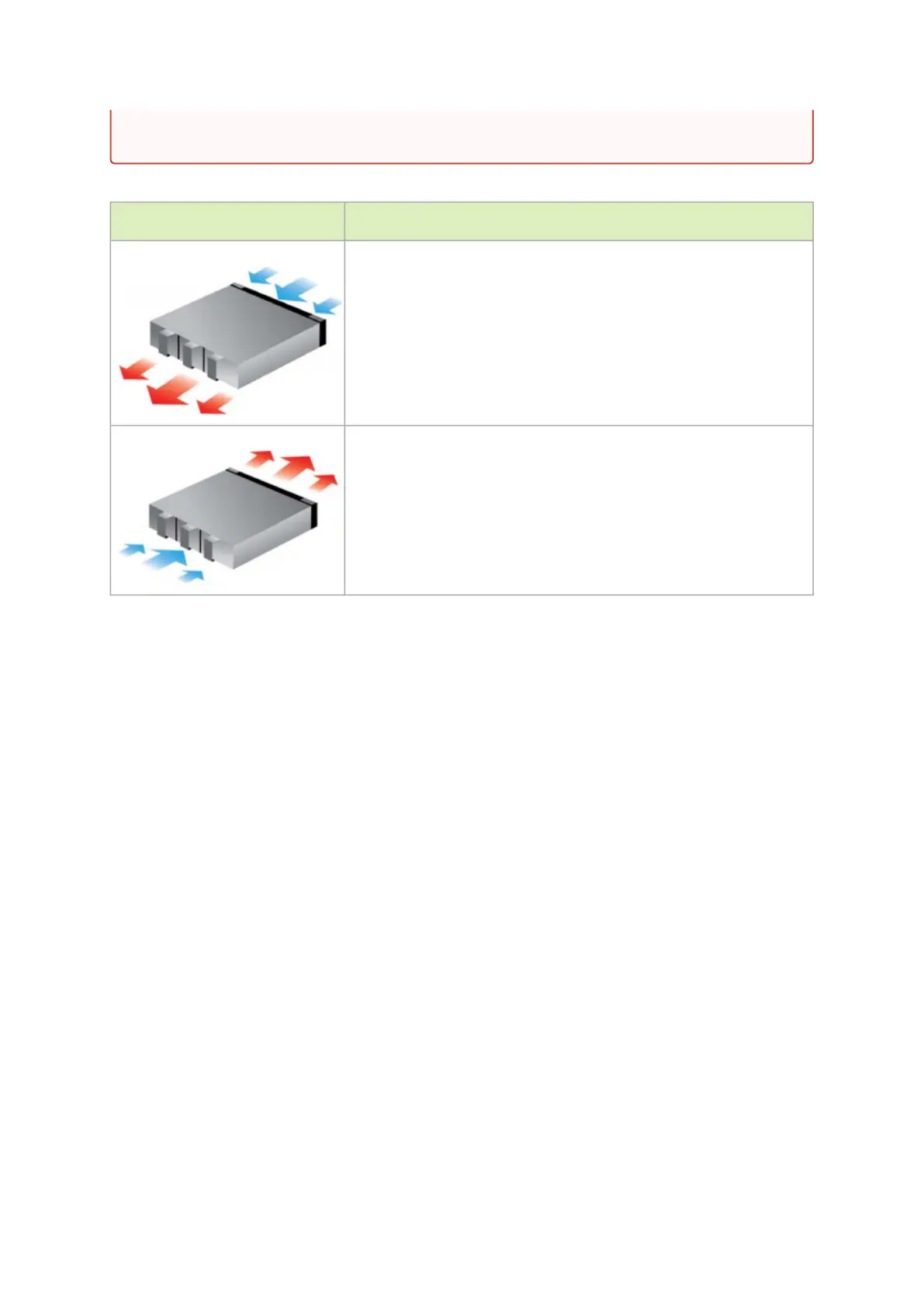
The table below provides an air flow color legend and respective OPN designation.
Direction Description and OPN Designation
Connector side inlet to power side outlet. Red latches are placed on the
power inlet side.
OPN designation is “-R”.
Power side inlet to connector side outlet. Blue latches are placed on the
power inlet side.
OPN designation is “-F”.
Package Contents
Before installing your new system, unpack it and check against the parts list below that all the parts
have been sent. Check the parts for visible damage that may have occurred during shipping.
The SN4600/SN4600C package content is as follows:
1 xSystem
1 xRail kit
1 xPower cable for each power supply unit – Type C13-C14
1xHarness: HAR000028 – Harness RS232 2M cable – DB9 to RJ-45
1 xCable retainer for each power supply unit
The SN4410/SN4700 package content is as follows:
1 xSystem
1 xRail kit
4 xPower cables:
2 x 250V 10A 1830MM C14 TO C15 power cable
2 x 110V 15A 1830MM C14 TO C15 UL power cable
1 x Harness: HAR000631 – Harness RS232 2M cable – DB9 to RJ-45
2 x Cable retainers for each power supply unit
All FRU components need to have the same air flow direction. A mismatch in the air flow
will affect the heat dissipation.
 Loading...