8
SOURCE WATER TEMPERATURE
ENTERING SOURCE WATER TEMPERATURE
The entering source water temperature range of operation for
the unit is 40° - 100°F (4.4°C to 38°C). The source temperature
drop (Delta T - ∆T) through the evaporator (heat exchanger)
will be approximately 8°F to 12°F (-13°C to -12°C).
If the source water temperature is outside this operating
range the HPWH unit’s Limit Thermostat will discontinue
heating operation until the entering source water temperature
returns to this operating range.
LOCATING THE WATER HEATER
INDOOR/OUTDOOR INSTALLATION
(Milder Climates)
Carefully choose a location for the HPWH unit. Placement is a very
important consideration for optimal performance and safety.
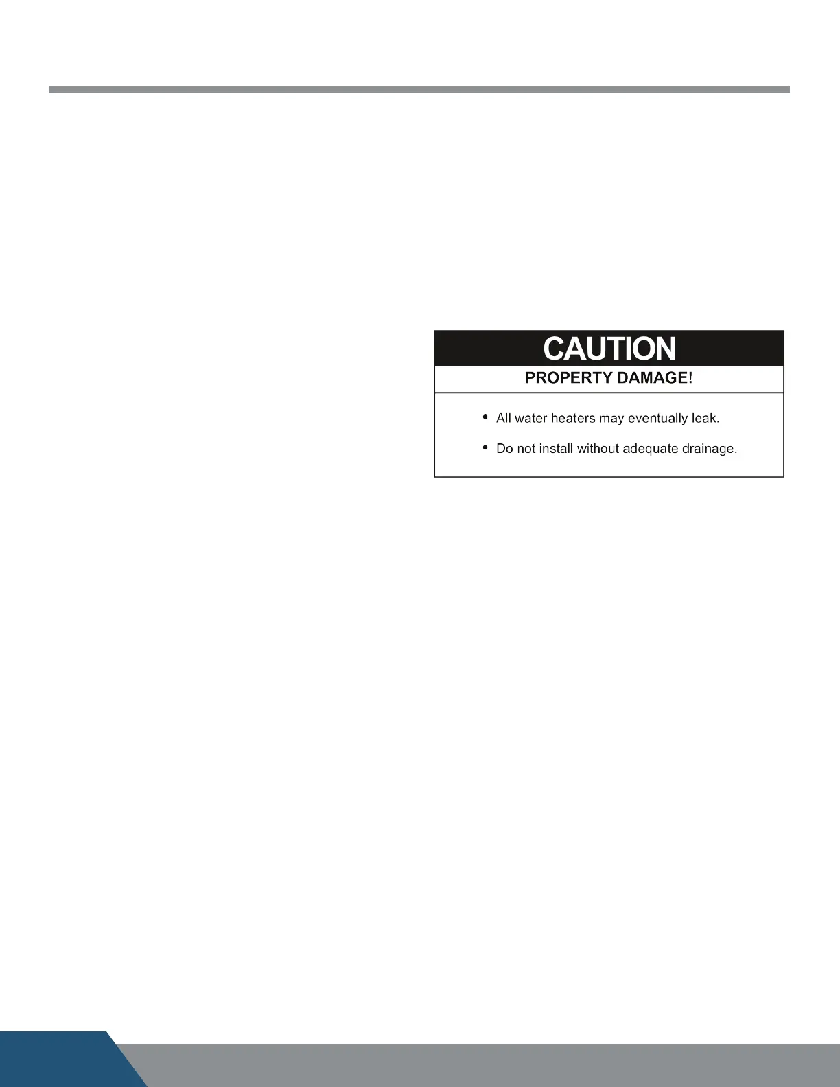
Locate the HPWH near a floor drain. The unit should be
located in an area where leakage from the HPWH unit or the
storage tank it is connected to will not result in damage to the
area adjacent to the water heater or to lower floors of the
structure. See Unit Placement on page 14.
FREEZING TEMPERATURES
The HPWH unit must not be installed in space where freezing
temperature will occur, without a low ambient air kit. Exposure
to freezing ambient temperatures below 32°F (0° C) may result
in severe damage to internal components. Damage caused by
exposure to freezing temperatures is not covered under the
limited warranty.
COASTAL REGIONS
Water-Source HPWHs have an optional Outdoor Rated Coating
that can be quoted at the time of purchase. This coating will
prevent premature wear on HPWHs. The epoxy and polyurethane
system has a salt spray/fog rating of 9,000 hours and performs
well in harsh environments ensuring the coatings never dull
and remain intact ensuring a durable nish.
HEAT SOURCE
The HPWH unit should be located where there is adequate
source water from which to extract waste heat and where the
source water cooling benet can be utilized when possible.
INSTALLATION REQUIREMENTS
Read all installation requirements in this manual before
installation begins. The installation must conform to these
instructions and all local and national code authority having
jurisdiction.
Costs to diagnose, perform service and repair damage caused
by installation errors are not covered under the limited warranty.
Costs to correct installation errors are not covered under the
limited warranty.
WATER TEMPERATURE
MAXIMUM SYSTEM TEMPERATURE
The HPWH units covered in this manual are capable of maintaining
a maximum system/storage tank temperature of 150°F (66°C).
Some commercial water heating applications may require
higher temperatures. Install a booster water heater downstream
from the storage tank for temperatures above 150°F (66°C).
See Figure 8 on page 16.
INLET & OUTLET WATER TEMPERATURE
The inlet (entering) water temperature operating range for
the HPWH is 40°F to 140°F (4.4°C to 60°C). The water temperature
rise (Delta T - ΔT) through the condenser (heat exchanger) will
be approximately 8°F to 12°F (4°C to 7°C).
Outlet water temperatures up to 152°F (67°C) are possible
during normal operation. Exposure to water temperatures
this high can cause serious bodily injury or death. See Mixing
Valves and Table 5 on pages 11 & 12.
Service & Installation Notes:
If the inlet (entering) water temperature is outside the operating
temperature range for extended periods the control
system may lock out on high or low refrigerant pressure
switch events/trips.
When the control system locks out on a refrigerant pressure
switch event the compressor will stop running, the blower and
circulation pump (on models equipped with factory installed
pump) will continue to operate. This is a hard lock out condition.
The control system is manually reset by cycling power to the
HPWH o and then on again.
The tank thermostat must not be set any higher than 150°F
(66°C) to prevent control system lock outs.
Ground water temperatures can fall below 50°F (10°C)
for extended periods during winter months in many regions.
For this reason the cold water supply lines and should not
be connected directly to the HPWH inlet or T tted into the
inlet (return) water piping. The cold water supply lines should
be connected directly to the storage tank only. See the Piping
Diagrams on page 29 in this manual for more information.
Model Volts/Phase/HZ
Compressor
MCA MOCP/MFS
LRA RLA
C25W
208-230/1/60 73 17.4 22 25
208-230/3/60 63 10.4 13 15
440-480/3/60 31 5.9 7 10
575/3/60 31 5.2 7 10
C60W
208-230/1/60 129 30.1 38 40
208-230/3/60 156 22.1 28 30
440-480/3/60 75 11 14 15
575/3/60 54 9 11 15
C90W
208-230/3/60 239 37.2 46 50
440-480/3/60 125 19.8 25 30
575/3/60 80 13.4 17 20
C125W
208-230/3/60 300 53 65 70
440-480/3/60 150 26.7 33 35
575/3/60 109 23.5 29 30
C185W
208-230/3/60 505 78 97 100
440-480/3/60 225 35 43 45
575/3/60 180 29.3 36 40
C250W
208-230/3/60 446 92.7 116 125
440-480/3/60 223 46.7 59 60
575/3/60 164 38.9 49 50