9
CLEARANCES
To ensure optimal performance a minimum of 30 inches
clearances required from the back, left and right sides of the
HPWH unit and any wall obstruction. A minimum of 36 inches
clearance on the front of the unit for access to the control box.
ELECTRICAL REQUIREMENTS
Ensure the power supply voltage and phase at the job site
matches the power supply ratings listed on the HPWH data
sticker label BEFORE INSTALLATION BEGINS.
The installation must conform with these instructions and the
local code authority having jurisdiction and the requirements
of the power company. In the absence of local codes,
the installation must comply with the current editions of
t he N a tional Electrical Code, ANSI/NFPA 70 or the Canadian
Electrical Code CSA C22.1.
Voltage applied to the HPWH should not vary more than +5%
to -10% of the voltage requirement listed on the HPWH rating
label for satisfactory operation.
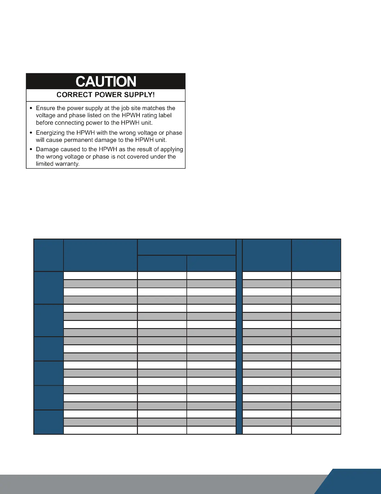
TABLE 2 - VOLTAGE & AMPERAGE RATINGS
Model Volts/Phase/HZ
Compressor
MCA MOCP/MFS
LRA RLA
C25W
208-230/1/60 73 17.4 22 25
208-230/3/60 63 10.4 13 15
440-480/3/60 31 5.9 7 10
575/3/60 31 5.2 7 10
C60W
208-230/1/60 129 30.1 38 40
208-230/3/60 156 22.1 28 30
440-480/3/60 75 11 14 15
575/3/60 54 9 11 15
C90W
208-230/3/60 239 37.2 46 50
440-480/3/60 125 19.8 25 30
575/3/60 80 13.4 17 20
C125W
208-230/3/60 300 53 65 70
440-480/3/60 150 26.7 33 35
575/3/60 109 23.5 29 30
C185W
208-230/3/60 505 78 97 100
440-480/3/60 225 35 43 45
575/3/60 180 29.3 36 40
C250W
208-230/3/60 446 92.7 116 125
440-480/3/60 223 46.7 59 60
575/3/60 164 38.9 49 50
LRA: Locked Rotor Amps RLA: Rated Load Amps
MCA: Maximum Current Ampacity MOCP: Minimum Overcurrent Protection