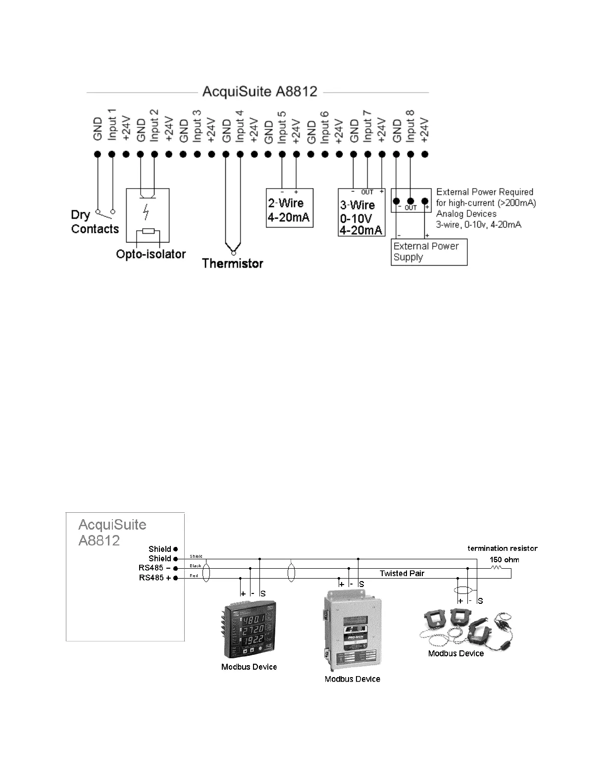
Step 3 – (optional) Connect any analog or pulse output sensors you may have. For Analog sensors, 0-10V or 4-20mA sensor
types are allowed. The combined power consumption of all the analog sensors attached to the AcquiSuite must not exceed
200mA. If more current is required, use an external power supply as shown in the wiring diagram for each input type later in
this section.
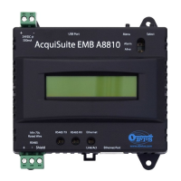
Step 4 (optional) - Connect the Modbus network loop as shown in the wiring diagram. Follow the manufacturer’s
instructions for installing and powering the Modbus devices. Verify that the Modbus address settings are unique for each
device (i.e., no two devices with the same address) and power up the device. Connect each device in the chain by “daisy-
chaining” the devices together . Observe + and - polarity on the Modbus devices. For more information about Modbus loops,
please read our Modbus FAQ.
Low Voltage analog, pulse, and RS485 wiring that enters electrical panels must have a minimum insulation rating that
exceeds the voltage inside the panel. In addition, other regulations may apply; consult the building codes in your area prior
to installation.
The RS485 port on the A8812 has a built in terminator. A 150 ohm termination resistor should be placed at the other end of
the RS485 loop, between the + and – wires. For more information about RS485 termination, read the Modbus FAQ.
Some Modbus devices do not use the same label notation as the AcquiSuite. Rather than +,-,S, Emon uses Low, High, and
Gnd. To attach an Emon meter, use + to high, - to low, and shield to gnd.
The AcquiSuite A8812 internal IO module (Analog and pulse inputs) uses Modbus address 250, and will show up in the
Modbus device count as a single Modbus device. Additional analog or pulse input IO modules may be added to the Modbus
loop as needed.
Page 8 A8812 AcquiSuite – Data Acquisition Server
Shop for Power Metering products online at:
1.800.561.8187
www.PowerMeterStore.ca