Step 5 - Power-up and diagnostics: Attach the power supply to the power input jack on the AcquiSuite, and plug the power
brick into a wall outlet. The power brick should be in a location that is accessible for connection and disconnection. After
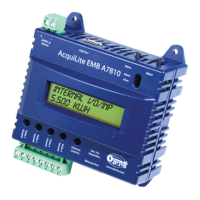
power is applied, the green “Alive” light in the upper right of the AcquiSuite should come on and the LCD display will
display a series of diagnostic screens ending with the following message on the LCD display (this boot sequence may require
up to 20 seconds to complete):
AcquiSuite Ready
192.168.40.50
This indicates that the AcquiSuite has loaded properly and is ready for configuration and connection to the network and
sensors. If the “Alive” light does not come on or the LCD display does not cycle to the above screen, verify that the power
cord is plugged in. If after cycling the power the unit still does not power up (or if an error message appears in the LCD
display) contact technical support. After the A8812 has been powered up for a minute, the green Alive LED should blink
slowly once per second during normal operation.
● Modbus TX/RX: The Modbus TX and RX LEDs blink to indicate data on the RS485/Modbus loop. The
RX led blinks only when data is received by the AcquiSuite
● Modem RTS: the modem is being monitored or operated by the AcquiSuite, off when the modem is idle.
This LED will be on when a dialout call is in progress, or when dialin is enabled and waiting for an
inbound call.
● Modem CD: the modem has a carrier connection to a remote system.
● Modem TX/RX: data is being sent or received on the modem.
● Alive: blinks once per second while the system is operating correctly.
● Alarm: blinks to indicate a problem.
● Inputs 1-8: in pulse or status mode, the LED is on when contacts are closed. In analog 4-20mA and 0-
10V mode, the led blinks quickly (2hz) to indicate an over-range alarm error. In 4-20mA mode when the
input current is less than 4mA, or in resistance mode where the input resistance is above 10Mohm, the led
will blink a pattern (blink, blink, off) to indicate a broken wire alarm.
● Ethernet Link/Act: On when connected to a hub or switch, off when not connected. Blinks when Lan
traffic is being sent or received.
● RS485 RX/TX. The 485TX led should blink slowly once per second during normal operation. The RX
led will blink when external Modbus devices communicate with the AcquiSuite.
● RF TX / RF RX: If the A8812 has a built-in ModHopper option with an on-board radio, the RF LEDs
will blink showing transmit and receive packets.
Step 6 Verify connected devices: To verify that the Modbus devices are installed and reporting correctly, use the Modbus
status utility on the AcquiSuite™ server. To do this test, follow these steps:
A. Press and release the menu (top) button on the AcquiSuite. The following will appear on the LCD display:
[Main Menu]
TCP/IP Config
B. Press the menu (top) button several more times until the LCD display shows the following message:
[Main Menu]
Modbus Status
C. Press the select (bottom) button on the server and the unit will begin the diagnosis of the Modbus loop.
After the check is completed, the unit will display the following message:
X devices OK
X fail, X new
D. Verify that the number of devices located by the server (the total of OK, fail and new) matches the number
of devices actually installed and connected. For a first time installation, all devices should appear as “new”.
The AcquiSuite A8812 Internal IO (pulse and analog inputs) appear as one device in this list.
Page 9 A8812 AcquiSuite – Data Acquisition Server
Shop for Power Metering products online at:
1.800.561.8187
www.PowerMeterStore.ca