Do you have a question about the Oceanic VEO 250 and is the answer not in the manual?
Overview of Dive Computers 101, covering theory, operation, and benefits of multilevel diving with Oceanic computers.
Gain understanding of computer function, advantages vs. tables, setup, operation, and feature selection for diving.
Sensors (Depth, Tank Pressure, Temperature) send data to the Analog to Digital (A/D) Converter.
The A/D Converter transforms analog sensor data into digital signals for processing.
Micro Processor calculates data and presents it to the diver via the LCD Display.
Basic dive tables use maximum depth for total time, rounding up depth, leading to conservative profiles.
Dive computers calculate more accurate profiles by performing frequent calculations based on real-time data.
Understand the Decompression Model utilized by Oceanic Dive Computers.
Understand tissue compartments and their graphical representation on an Oceanic Dive Computer.
Theory validated by 1987 DSAT experiments, forming the basis for Oceanic PDC algorithms.
PDC simulates nitrogen absorption using a mathematical model based on latest decompression research.
Using a PDC, like dive tables, doesn't guarantee avoidance of decompression sickness.
Individual physiology varies; no machine can predict exact body reaction to dive profiles.
PDC tracks 12 tissue compartments (5-480 min halftimes); bar graph shows the controlling compartment.
Tissue Loading Bar Graph visualized as 12 transparent layers; fastest filling compartment is visible.
Compartments can simultaneously absorb nitrogen or off-gas, depending on their state.
This feature enables multilevel diving, a key contribution of Oceanic PDCs.
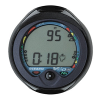
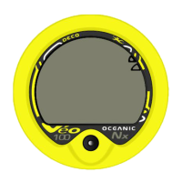
Identify numeric and graphic displays of the Veo 100 Nx.
Understand the function of the Control Button.
Identify and understand information presented via bar graphs.
Identify and understand low battery power condition displays.
Understand formats, ranges, and values of each display element to prevent errors.
The Control Button selects display options and accesses specific information.
The Control Button is also used to enter device settings.
Represents nitrogen tissue loading, showing no decompression or decompression status.
Conveniently monitors proximity to the No Decompression Limit.
Segments increase with depth/time, recede with ascent, indicating allowed NDL for multilevel dives.
Monitors 12 compartments; displays the active one in No Decompression, Caution, or Decompression zones.
Use the No Decompression Caution Zone for a wider margin of protection.
Oceanic suggests the Tissue Loading Bar Graph remain in the No Decompression zone when exiting water.
Choose personal caution zone based on age, physique, weight to reduce risk of DCS.
O2 Bar Graph appears only when FO2 is set to a value other than 'Air'.
Represents oxygen loading, showing max per dive or 24-hour accumulated oxygen.
Segments increase with exposure, recede with decrease, indicating allowed additional exposure.
PDC's VARI (bar graph) shows ascent speed, acting as an ascent speedometer.
Provides a visual representation of ascent speed.
Exceeding max ascent rate triggers the 'Too Fast' Alarm Zone on the bar graph.
Alerted by flashing segments; stops when ascent rate slows.
Segments represent speeds relative to 60 FT: details for shallower and deeper than 60 FT.
Current depth display shows 0-330 FT (99.9 M) in 1 FT (0.1 M) increments during a dive.
Access alternate displays to show Maximum Depth reached during the dive.
During a Decompression Dive, the required Ceiling Stop Depth is displayed in the center.
Main Time in lower, second time in center/right, both marked by clock icon.
Time of Day can be set to 12-hour (AM/PM) or 24-hour format.
Time displays use hour:minute format (e.g., 1:16 is 1 hr 16 min, not 116 min).
Maximum time at current depth before entering a decompression situation.
Calculated based on modeled nitrogen absorption/release by tissue compartments.
The closest compartment to its maximum nitrogen level is the controlling factor for depth.
Resulting NDL time displayed numerically with icon and graphically on TLBG.
Dive Computer constantly monitors no-decompression status and oxygen exposure.
Display shows the most critical time (least available) for current moment.
Uses one CR 2450 Lithium cell: 300 hours continuous or 50 activation periods.
Approximately 50 dives if 1 dive is performed per activation.
Approximately 150 dives if 3 dives are performed per activation.
A Battery Indicator shows the current battery condition.
Indicator shown in Surface Mode when power is sufficient; not shown in Dive Mode.
At 75% power consumed, indicator shows lower bar and flashes outline as a warning.
At critically low voltage, indicator flashes 5 times then unit shuts down.
On activation with low battery, 'bAT' flashes with indicator for 5s before shutdown.
If low battery occurs mid-dive, operation continues; indicator appears in Surface Mode.
Identify various display components: icons, graphics for PO2, depth, TLBG, VARI, time, battery, O2.
Understand how to manually activate the Dive Computer.
Understand how to access the Serial Number and Firmware Revision.
Understand Veo 100 Nx calibration and operation at high altitude.
Understand the information displayed during the Surface Sequence.
Access Set Mode and modify personal settings.
Press and release the button to manually activate the Veo 100 Nx.
Upon activation, unit enters Diagnostic Mode with segment test and countdown.
Diagnostic Mode checks display and battery voltage for proper function.
Hold button during diagnostic countdown to view Serial Number and Firmware Revision.
Activates by checking ambient pressure and calibrating depth to zero; recalibrates at elevations > 2000 ft.
Decreasing atmospheric pressure at altitude affects barometric pressure, causing shallower depth readings without compensation.
Veo 100 Nx automatically compensates for altitudes 2,000-14,000 ft, adjusting limits for caution.
Senses ambient pressure upon activation, every 15 min (active) or 30 min (inactive).
Recalibrates at 2000 ft (fresh water depth) and readjusts limits every 1000 ft. Resets upon returning to lower altitudes.
Unit scrolls through Surface, Fly, DeSat, and Plan modes on the surface.
During Surface Sequence scrolling, access Log Mode and Set Mode via the button.
Surface Mode identified by Surface Time icon, follows Diagnostic Mode after Activation.
Displays Dive Number, Temperature, Time of Day, Battery Indicator, and Surface Time.
Veo 100 Nx can auto-activate via Wet Contact if Wet Activation is set ON.
Auto-deactivates after 2 hours with no dive; reactivates if wet contacts remain bridged.
Access settings sequentially or jump to specific items, bypassing others.
If inactive for 2 minutes in Set Mode, unit reverts to Surface Mode.
Depress the button for 2 seconds while Surface Sequence scrolls to access Set Mode.
Upon entry, Set FO2 screen appears with Set Point flashing.
Momentarily press/release button to modify settings.
Depress button for 2 seconds to accept Set Point and advance.
On activation, FO2 defaults to AIR; adjustable from 21-50% in 1% increments.
Press/release button to cycle FO2 from 21-50% (1% increments), then back to AIR.
Display shows Max Depth for PO2 of 1.60 ATA or Alarm Set Point; no depth for AIR.
Depress button for 2 seconds to accept FO2 Set Point and advance to Set Wet Activation.
Factory set ON; can be set OFF to prevent inadvertent activation during travel/storage.
When ON, unit auto-activates and enters Dive Mode upon water immersion.
After accepting FO2, Set Wet Activation screen appears with Set Point flashing.
Press/release button (short) to toggle Wet Activation between ON and OFF.
Depress button for 2 seconds to accept Wet Activation and advance to Set Units.
Factory set to Imperial; can be changed to Metric.
After Wet Activation, Set Units screen appears with Set Point flashing.
Press/release button (short) to toggle between Imperial (FT/F) and Metric (M/C) units.
Depress button for 2 seconds to accept Units and advance to Set Hour Format.
Factory set for 12 Hour; can be set for 24 Hour format.
After setting Units, Set Hour Format screen appears with Set Point flashing.
Press/release button (short) to toggle between 12-hour and 24-hour formats.
Depress button for 2 seconds to accept Hour Format and advance to Set Time.
Set local time to 0:00-12:59 AM/PM or 0:00-23:59.
After accepting Hour Format, Set Time screen appears with Hour Set Point flashing.
Press/release button to advance Hour Set Point in 1-hour increments.
Depress button 2s to accept Hour Set Point; Minutes Set Point flashes.
Press/release button to advance Minute Set Point in 1-minute increments.
Depress button 2s to accept Minute Set Point and advance to Set PO2 Alarm.
Factory set 1.60 ATA; adjustable 1.20-1.60 ATA in 0.10 ATA increments.
After setting Time, Set PO2 Alarm screen appears with Set Point flashing.
Press/release button to advance PO2 Alarm setting in 0.10 ATA increments.
Depress button 2s to accept PO2 Alarm Set Point and advance to Set FO2 Default.
Feature factory set ON; can be set OFF. Effects described later.
After PO2 Alarm, Set FO2 50% Default screen appears with Set Point flashing.
Press/release button (short) to toggle FO2 50% Default between ON and OFF.
Depress button 2s to accept Set Point and advance to Surface Mode/Sequence.
Manually activate Veo 100 Nx; modify settings: FO2, Wet Activation, Units, Hour, Time, PO2 Alarm, 50% Default.
Perform pre-dive planning.
PDPS provides theoretical dive times for depths 30-190 FT (10 FT increments) before the first dive.
NDLs shown only if >= 3 min theoretical dive time available at depth, considering 60 FPM descent.
Review PDPS before every dive to plan and avoid exceeding NDL or O2 limits.
PDPS shows adjusted dive times for repetitive dives based on residual nitrogen/oxygen.
Plan a dive to 100 feet and determine the no-deco time allowed.
Understand the underwater use of the control button.
Understand the information provided on Dive Mode displays.
Establish personal conservatism by monitoring the Tissue Loading Bar Graph.
Understand function and info during a no-decompression Safety Stop.
Select from up to 4 displays (Depth, DTR, etc.) by pressing/releasing button (< 2s).
In cautionary modes, main display shows relevant info; other screens revert to main after 3s.
Unit automatically enters No-Deco Dive Mode upon descending to 5 FT (1.5 M).
Display #1 shows Current Depth, Dive Time Remaining (with icon), and bar graphs.
Press/release button (< 2s) to switch to No Deco Dive Main Display #2.
Display #2 shows Current Depth, Max Depth, Elapsed Time, DTR (with icon), and bar graphs.
Press/release button (< 2s) to switch to No Deco Dive Main Display #3.
Display #3 shows Current Depth, Temp, Time of Day, DTR (with icon), and bar graphs.
Press/release button (< 2s) to switch to No Deco Dive Main Display #4.
Display #4 does not appear when FO2 is set for AIR.
Display #4 shows Current Depth, PO2 value/graphic, DTR (with icon), and bar graphs.
Press/release button (< 2s) to return to No Deco Dive Main Display #1.
Ascending causes TLBG segments to recede, showing multilevel diving capability.
Backing off the bar graph (fewer segments) establishes personal conservatism.
In Decompression Mode, do not ascend fully until TLBG is in the No Decompression Zone.
Make every effort to complete ascents with the TLBG inside the No Decompression Zone.
Choose personal caution zone based on age, physique, weight, training, experience to reduce DCS risk.
Appears on NDL dives exceeding 30 FT (9 M) when ascending to 20 FT (6 M).
A stop between 10-20 FT (3-6 M) is recommended before ascent.
Display continues until countdown ends, descent below 30 FT, or surfacing.
No penalty for surfacing before completing the Safety Stop.
Anticipate potential unit failure; don't push NDL/O2 limits or enter Decompression.
A backup instrument system is highly recommended if unit failure jeopardizes safety or trip.
Fill No-Deco Display #1: Depth 85ft, DTR 36min, TLBG 5 segments, VARI 2 segments.
Fill No-Deco Display #2: Depth 85ft, DTR 36min, TLBG 5 seg, VARI 2 seg, Max Depth 95ft, Elapsed 16min.
Fill No-Deco Display #3: Depth 85ft, DTR 36min, TLBG 5 seg, VARI 2 seg, Temp 82F, Time 9:25.
Understand information displayed in Post-Dive Surface Mode.
Understand info and operation during the Transition Period.
Understand info and operation following the Transition Period.
Understand the Time to Fly and Desaturation Time Displays.
Conduct Pre-Dive Planning for a repetitive dive.
Access and understand information displayed in Log Mode.
Understand information and operation after two hours on the surface.
Unit enters Surface Mode and begins counting Surface Interval upon ascending to 2 FT (0.6 M) or shallower.
First 10 mins: Dive #, Temp, Time of Day, Battery, Surface Interval, TLBG, O2 BG (if Nitrox).
During Transition Period, only Log Mode is accessible; others are not.
Press/release button (< 2s) to view the dive log during the transition period.
Descending during Transition Period continues the dive; surface time is not added to Elapsed Dive Time.
After 10 mins, Surface Mode/SI colon stop flashing, indicating new dive on subsequent descent.
For 2 hours post-surface, info displayed as Surface Sequence (Surface > Fly > Sat > Plan).
Full access to Log and Set modes is available after the transition period.
Time to Fly and DeSat Timers start counting down 10 mins post-dive (after Transition Period).
FLY and DeSat countdowns start at 23:50 (hr:min).
If violation occurs, FLY shows dash (-); DeSat time is not displayed.
Time to Fly counter helps decide when it's safe to fly or travel to higher elevations.
After 12hr SI, can fly if dive profiles did not involve decompression.
Wait 24 hours after last dive if decompression or multi-day profile was involved.
Post-dive PDPS provides adjusted NDLs based on residual nitrogen from current and previous dives.
Stores up to 12 dives; full log overwrites oldest entries. Transfer data to logbook.
Log data retained on battery removal/replacement; lost on factory service/calibration.
First dive after activation is #1; multiple #1 dives can exist in the log.
3 screens per dive (ID, Dive Data, O2 Data); dives shown most recent to oldest.
Momentarily press/release button (< 2s) during Surface Sequence to access Log Mode.
First screen shows Log icon, Dive #, and Time of Day for the most recent dive.
While viewing Preview, press/release button momentarily to view the second screen.
Shows Max Depth, Min Temp, SI, Elapsed Time, VARI, TLBG (flashing max loading).
While viewing Preview, press/release button momentarily to view the third screen.
Shows FO2/Set Point, Max PO2, O2BG (oxygen loading).
Press/release button (< 2s) to access the first screen of the previous dive's log.
After 2 hours, Surface Sequence stops; Time to Fly/DeSat screens alternate (3s each) until 0:00 or new dive.
Press/release button to reactivate Surface Sequence to access other modes/settings.
Unit reverts to Time to Fly/DeSat countdowns after 2 hours if button is not pressed.
SI times > 9:59 displayed as Hours (10-, 11-, 12-).
H2O graphic in Surface/Fly/Desat modes means wet contacts are bridged; rinse and dry unit.
Contacts are located in the button stem and back of the case.
H2O graphic disappears once the unit is dry.
If not cleaned/dried before 0:00 or new dive, unit shuts off then auto-reactivates.
H2O graphic appears in place of Dive Number in Surface Mode during Surface Sequence.
If no dive after activation, unit shuts off after 2h, reactivates if wet, until cleaned.
Access Log Book; identify Dive #, Time of Day, Max Depth, Elapsed Time, SI for the most recent dive.
Understand info and bar graphs when diving with Nitrox.
Understand default Nitrox settings following a dive.
Understand info and procedures for high PO2 and O2 accumulation situations.
Understand information displayed in Decompression Dive Mode.
Understand how to manage a Decompression Dive.
Understand situations leading to Dive Computer entering Violation Mode.
Understand info and procedures for Violation Mode situations.
After activation, operates as AIR computer unless FO2 is set to 21-50%, then shows oxygen info.
AIR setting uses 21% oxygen internally for loading; O2 displays/graphs hidden unless FO2 is numerical (21-50).
After Nitrox dive, unit stays Nitrox for 24h. Can set FO2 to 21% for AIR use.
Setting FO2 to 21% persists for subsequent Nitrox dives until changed or unit reactivates.
PDPS shows NDLs (nitrogen-controlled) or OTLs (oxygen-controlled) based on dive history.
Maximum Operating Depth for the selected FO2 setting (1.60 ATA PO2) is displayed.
TLBG displayed means nitrogen-controlled; O2BG/symbol means oxygen-controlled.
PO2 >= 1.40 ATA or < 0.20 ATA from Alarm Set Point triggers warning: PO2 value, symbol, O2 segment, UP Arrow.
If PO2 increases, value rises to 5.50 ATA. At 1.60 ATA or Alarm Set Point, indicators flash as a warning.
O2 Bar Graph shows oxygen accumulated per dive or over 24 hours, whichever is greater.
O2 Bar Graph monitors proximity to oxygen exposure limits, providing a margin of protection.
Exceeding O2 limits (single exposure or 24hr) sets O2 DTR to 0:00 and O2 BG to Danger Zone.
UP Arrow and full O2 Bar Graph flash as a warning until oxygen level decreases below the limit.
Oceanic PDCs are sophisticated instruments that help avoid and manage decompression beyond recreational diving.
Upon entering Decompression Mode, the Mode icon changes from No Deco to Deco.
UP Arrow and Deco Bar flash if deeper than 10 FT (3 M) past Required Stop Depth.
Arrows and Bar appear solid when within 10 FT (3 M) of and below the required Stop Depth.
Includes stop times, and vertical ascent time at 60 FPM (>60ft) and 30 FPM (<=60ft).
Ascend safely to the Required Ceiling Stop Depth and decompress for the indicated Stop Time.
Stay slightly deeper than indicated stop depth until the next shallower stop depth appears.
Slowly ascend to, but not shallower than, the indicated ceiling stop depth.
Credit Time depends on depth; stay deeper than indicated Stop Depth until next shallower stop appears.
In Decompression Mode, alternate displays revert to Main after 3 seconds.
Enters Violation Mode when situation exceeds capacity to predict ascent procedure.
Exceeding limits triggers visual/audible warnings and special Violation Modes.
Entering Violation Mode disables deco/O2 monitoring for 24 hours post-dive.
Staying above required Deco Stop Depth for > 5 minutes triggers Violation Mode.
Decompression requires Ceiling Stop Depth > 60 FT (21 M) triggers Violation Mode.
Exceeding max operating depth of 330 FT (99 M) triggers Violation Mode.
Operates with limited functions in Violation Gauge Mode during dive and 24h post-dive.
Violation Gauge Mode acts as a digital instrument without deco/O2 monitoring.
Displays: Current Depth, Max Depth, Elapsed Time, VARI. TLBG/O2BG flash as warning.
Alternate Displays from Deco Dive Mode can be accessed in Violation Modes.
Alternate Displays revert to Main after 3s unless another is viewed.
RESET feature clears data including Nitrogen/Oxygen calculations and Log Mode entries.
WARNING: Resetting for repetitive dives by same diver can cause serious injury or death.
Fill Deco Display #1: Depth 21ft, TAT 9min, Deco Ceiling 20ft, Stop Time 2min, TLBG 8 seg, O2 BG 3 seg.
Describe care and cleaning procedures for the dive computer.
Identify inspection and service interval.
Understand basic practices for battery replacement.
Understand the procedure for pre-dive inspection of the Dive Computer.
Protect from shock, temp, chemicals, tampering. Use lens protector; small scratches disappear underwater.
Rinse in fresh water daily; check depth sensor/button for debris.
Use lukewarm water or vinegar/water bath for salt crystals. Rinse, towel dry before storing.
Transport and store unit cool, dry, and protected.
Annual inspection by Authorized Dealer required for 2-year warranty (within 30 days of 1yr mark).
Oceanic recommends annual checks. Costs not covered by 2-year warranty.
Open Battery Compartment only in a dry, clean environment to prevent moisture/dust ingress.
Change battery in environment matching local temp/humidity to prevent moisture.
NOTE: Retain N2/O2 calculations and settings for repetitive dives if new battery inserted within 8 seconds.
Activate unit and observe full diagnostic/battery check entering Surface Mode.
Observe LCD for consistent clarity and sharp contrast throughout the screen.
WARNING: Missing/dim display or low battery indicates return to dealer for evaluation.
How often inspected? Battery change time for data retention? What to do if pre-dive inspection finds a problem?
Read and understand the Operating Manual for your specific model PDC before diving.
PDCs for recreational divers with recognized SCUBA course and knowledge of risks.
Oxygen features for divers with recognized Nitrox course and knowledge of risks.
If unsure about use or have questions, seek instruction from your Authorized Oceanic Dealer.
If activation/diagnostic display/function varies from manual, return unit to dealer for inspection.
Oceanic strongly recommends not diving with a low battery condition until replaced.
Before Nitrox dives, verify or set FO2 Set Point to match the Nitrox mix percentage.
PDPS predicted times may be less than indicated due to gas quantity, consumption, or O2 accumulation.
Review PDPS before every dive to plan and avoid exceeding NDL or O2 exposure.
Keep bar graphs in normal zones to reduce risk of DCS, O2 toxicity, and fast ascent rates.
Never share or exchange a Dive Computer with another diver, or use it for repetitive dives.
PDC capabilities do not imply approval to exceed defined recreational dive profile limits.
Always plan each dive.
Always limit your dive to your training and experience level.
Always make your deepest dive first.
Always make the deepest part of every dive first.
Check your Dive Computer often during the dive.
Do a safety stop on every dive.
Allow an adequate surface interval between each dive.
Allow adequate surface intervals between days (within 12h or until cleared).
Diving > 130 FT (39 M) requires special training, equipment, support, and increases DCS risk.
Decompression diving or diving deeper than 130 FT significantly increases DCS risk.
Decompression diving is hazardous and increases DCS risk, even with computer calculations.
Using a Dive Computer, like dive tables, is not a guarantee against decompression sickness.
1990 UHMS guidelines minimize DCS risk from flying too soon after diving.
UHMS suggests 24h wait after last dive to fly (up to 8000 ft cabin pressure).
Exception: If <2h total dive time in last 48h, a 12h SI before flying is recommended.
After dives with decompression stops, delay flying for at least 24h, preferably 48h.
DAN position: 12h SI minimum for reasonable assurance of remaining symptom-free when flying post-dive.
Divers making daily/multiple dives or requiring deco stops should wait >12h SI before flight.
UHMS/DAN agree no flying rule guarantees prevention of DCS. Guidelines are best estimates for most divers.
After single no-deco dive, wait 12 hours before exposure to pressures at 1000 ft (305m) or higher.
For repetitive dives/days, increase interval to min 24h. Land travel to higher elevations is altitude exposure.
Technology is not a substitute for common sense; computer provides data, not knowledge.
Dive Computer does not measure body tissue or blood composition.
Oceanic PDCs are cornerstones of innovation, pioneering industry standards in design and technology.
Overview of additional Oceanic PDC models to understand basic differences.
Veo 180 features: Audible Alarm w/ LED, SmartGlo Backlighting, OceanLog PC Interface, Digital Gauge Mode, Date Stamp, 24 Dive Log.
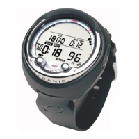
Adds to Veo 180: 2-Button Operation, On-Unit Simulator, Alarms for Max Depth/Elapsed Time/TLBG, Backlight Duration, PC Sampling Rate.
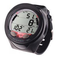
Adds to Veo 250: Air Integration (cylinder pressure), DTR with Air Time Remaining, Turn-Around Pressure Alarm.
Adds to Pro Plus 2: Wireless Air Integration (3 transmitters), 3 Mix Nitrox, Buddy Pressure Check, Alpha Numeric Display, Adj. Safety Stop, Conservative Factor, Free-Dive, 512K Memory.
ATOM 2.0 has VT3 features in a wristwatch, suitable for wetsuits or suits.
Includes Alternate Time Zone, Stopwatch, Lap Timer, Daily Alarm, Countdown Timer.
| Display Type | LCD |
|---|---|
| User Replaceable Battery | Yes |
| Number of Buttons | 4 |
| Dive Log Capacity | 24 dives |
| Audible Alarms | Yes |
| Ascent Rate Indicator | Yes |
| Operating Modes | Air, Nitrox, Gauge |
| Battery Type | CR2450 |
| Backlight | Yes |
| Logbook | Yes |
| Nitrox Compatibility | Yes, up to 50% |
| Dimensions | 85mm x 60mm x 25mm |
| Battery Life | Approximately 300 dive hours |