MINI6600
TM
Mobile Digital C-Arm Service Manual - Periodic Maintenance
PS1 (5V and 12V)
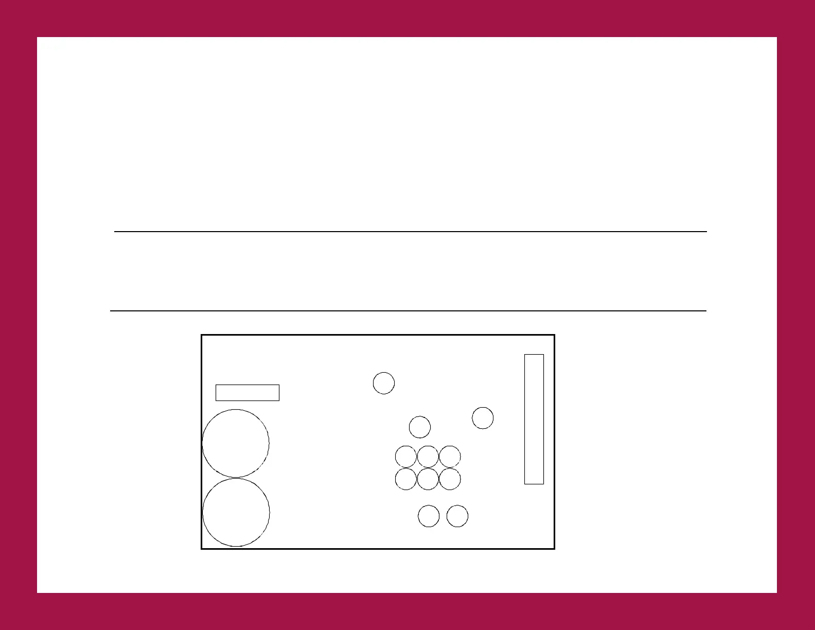
1. Measure the voltages at the following test points on the Video Switching PCB and adjust as required with R53
(+5) and R21 (+12) on PS1. Refer to FIGURE 2 in the Power Distribution section of the service manual (00-
878315) for the location of PS1. Refer to FIGURE 2 below for locations of R53 and R21.
2. The Video Switching PCB is located on the inside of the hinged rear panel of the electronics box (Refer to
FIGURE 4 in the Power Distribution section of the service manual (00-878315)).
GND TO ADJUST MEASUREMENT TOLERANCE
TP25 TP24 Not Adjustable - 5.0 VDC ±0.75 VDC
TP25 TP27 Adjust PS1 R53 (OUT1) + 5.0 VDC ±0.75 VDC
TP25 TP28 Adjust PS1 R21 (OUT 2) +12 VDC ±1 VDC
TP25 TP19 Not Adjustable - 12 VDC ±1 VDC
TABLE 3
FIGURE 2 - System Power Supply PS1 (+5V, -5V, +12V, -12V)
F1
250V 4A
FAST BLOW
PS1 P3
OUT 1
V ADJ
R53
DO NOT
ADJUST
R43
C28
C30
C32 C29 C42
C31
C18
OUT 2
V ADJ
R21
C5
C51