Do you have a question about the OHAUS 3000 Series T31P and is the answer not in the manual?
Overview of the service manual's purpose and chapter contents.
Requirements for the service area, including ESD protection and environmental controls.
Lists specialized and standard tools needed for indicator servicing, including lists of each.
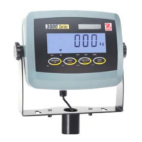
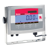
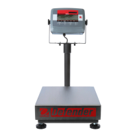
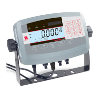
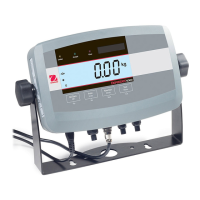
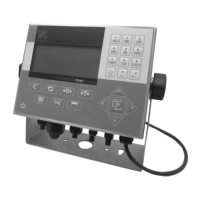
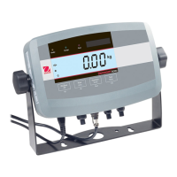
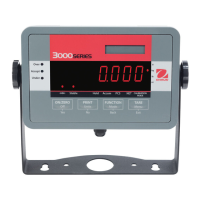
Details technical specifications for T31P and T31XW models, including capacity, resolution, and dimensions.
Instructions for opening the indicator housing for T31P and T31XW models.
Explains jumper settings for 4-wire and 6-wire load cells.
Details the RS232 communication port, connectors, and pin configuration for T31P and T31XW.
Covers basic operation, including power supply types and battery management.
Describes the indicator display, symbols, and control buttons.
Procedure for turning the indicator on and the initial self-test.
Procedure for turning the indicator off using the ON/ZERO/Off button.
Guide to navigating the indicator's menu structure using control buttons.
Outlines procedures for span and linearity calibration, including preliminary steps and GEO factor adjustment.
Explains the GEO factor for gravity compensation and how to adjust it.
Details the two-point process for calibrating the scale's span.
Describes the three-point process for calibrating the scale's linearity.
Covers RS232 communication setup, parameters, and commands.
Guides users through setting baud rate, parity, stop bits, and handshake for RS232.
Lists serial interface commands for controlling indicator functions via RS232.
Defines the default serial output format for data transmitted via RS232.
Explains the Legal For Trade mode, its limitations, and how to enable/disable it.
Introduces the troubleshooting section and diagnostic guide.
Provides steps for visually inspecting the indicator for damage and signs of abuse.
Presents a guide to help locate problems and suggests remedies based on symptoms.
Guidelines for regular care and cleaning of the indicator to ensure longevity.
A checklist of regular inspection and maintenance tasks for the indicator.
General advice on component replacement and contacting Ohaus for support.
Step-by-step instructions for replacing the main PCB in the indicator.
Procedure for replacing the set of cables connecting the PCB to various components.
Instructions for replacing the function label and membrane switch assembly.
Detailed steps for replacing the power supply unit in the T31XW model.
Step-by-step guide for replacing the rechargeable battery in the T31P model.
General guidance on performing operational and performance tests before and after servicing.
Procedure to verify the functionality of the indicator's electronic circuitry and power source.
Tests performed using a known scale base and test mass to verify performance.
Tests the indicator's response to overload and underload conditions.
Alternative tests using a load cell simulator if a scale base is unavailable.
Checks if the indicator retains calibration settings after power cycles.
Verifies RS232 communication and print function with external devices.
Exploded view and parts list for the T31P indicator's housing and internal components.
Exploded view and parts list for the T31XW indicator's housing and internal components.
| Model | T31P |
|---|---|
| Series | 3000 Series |
| Brand | OHAUS |
| Readability | 1 g |
| Display | LCD |
| Legal for Trade | Yes |
| Calibration | External calibration |
| Housing | ABS Plastic |
| Operating Temperature | 0 °C to 40 °C |
| Platform Construction | Stainless steel |
| Display Type | LCD |
| Capacity | 30000 g |
| Power Supply | AC adapter |
| Maximum Capacity | 3000 g |
| Power | AC adapter |