This document is an operation and maintenance manual for Oilon GP-600 M and 700 M-III series burners, equipped with WDx00 and FGR (UL) systems. The manual, dated 6 April 2023, provides comprehensive instructions for the installation, commissioning, operation, and maintenance of these industrial burners.
Function Description
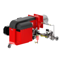
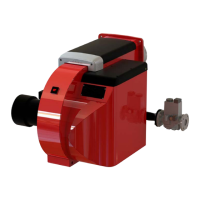
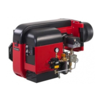
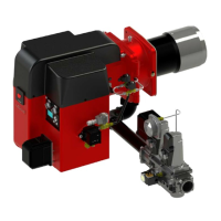
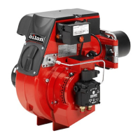
The Oilon GP-600 M and 700 M-III series are automatic forced draught burners designed for various heating appliances, including warm and hot water boilers, steam boilers, hot air generators, and process heating. They are specifically engineered to handle furnaces with high back pressure. The burners are typically mounted horizontally and are designed for operation up to 1,640 ft above sea level for the burner itself and 3280 ft for electrical equipment.
The WiseDrive system controls and supervises burner operation. In WD200 systems, an O2 module can be integrated to enhance combustion efficiency. The burner control unit adjusts the fuel and air ratio, as well as solenoid valves, to maintain optimal combustion. Flue gas recirculation (FGR) is an optional feature that reduces NOx emissions by recirculating a portion of flue gas back into the combustion chamber, lowering flame temperature.
The burner control system includes:
- Burner control and safety functions
- Electronic fuel/air ratio control
- Gas valve proving
- Capacity controller
- Fan variable speed drive control (WD200)
- Residual oxygen control (WD200)
- Boiler cold start thermal shock protection
- Fuel flow meter (WD200)
- Burner efficiency measuring (WD200)
- Start-up and running time counters
- Fault and lockout history
- Real-time clock
- Bus interface
Servomotors are used to drive fuel regulators and other actuating devices, ensuring precise control over the combustion process. The combustion air system provides the necessary air pressure and volume for efficient combustion, with a variable speed drive (VSD) adjusting air pressure based on the burner's capacity.
Important Technical Specifications
Burner Data (Gas)
| Burner Model |
Capacity, MMBtu/h |
Burner Motor (3~ 208–600 V 60 Hz) Output, hp |
Burner Motor (3~ 208–600 V 60 Hz) Current, A/460 V |
Burner Motor (3~ 208–600 V 60 Hz) Speed, rpm |
Weight, lbs* |
| GP-600 M |
3.7–25.6 |
20.0 |
23.5 |
3,510 |
1014 |
| GP-700 M |
4.5–31.8 |
25 |
31 |
3,510 |
1,179 |
| GP-700 M-II |
5.1–36.0 |
30 |
35.8 |
3,510 |
1,246 |
| GP-700 M-III |
5.7–39.8 |
40 (with variable speed drive) |
45 |
2,970** |
1,488 |
*Burner only. Weight varies depending on delivery content.
**The frequency must be converted to 50 Hz. For 700 M-III burners with 60-Hz configuration, use 50 Hz instead of nominal frequency, ensuring motor rpm does not exceed 3000.
Gas Use:
- Natural gas is standard. For other gases, consult the manufacturer.
- Gas inlet pressure to burner max: Natural gas: 8 - 200 "W.C., LPG: 11 - 200 "W.C.
- Max. demand for combustion air, gas use: 13.5 cfh/MBtu
- Efficiency, natural gas: 35.31 ft³n/h ≈ 13.5 MBtu efficiency (heat value 961.91 Btu/ft³)
- Performance, natural gas: 950 - 1050 btu/sc.ft
Electrical:
- Control voltage: 115 V (-15%...+10%) 50 Hz / 60 Hz 1-phase
- Motor voltage options: 220 V, 400 V, 460 V, 575 V (all 60 Hz 3-phase)
Burner Control (LMV5...):
- Mains voltage: 120 VAC -15/+10 %
- Power consumption: < 30 W
- Permissible operation ambient temperature: -4...+140 °F
- Degree of protection: NEMA 1
O2 Module (PLL52...):
- Mains voltage, sensor heating: 110 VAC -15/+10 %
- Mains voltage: 2 x 12 VAC
- Power consumption: 4 VA
- Permissible ambient temperature: -4...+140 °F
- Protection degree: NEMA 3
Oxygen Sensor (QGO20...):
- Measuring cell: Ceramic zirconium dioxide cell
- Measuring cell temperature: 1292 °F ±122 °F
- Measuring range: 0.2…20.9 % O2
- Max. temperature, flue gas: +572 °F
- Protection degree: NEMA 2
Flame Detector (QRI):
- Operation type: Continuous
- Supply voltage, operation: 14 VDC ±5%
- Signal voltage: 0–5 VDC
- Connected detector cable max. length: 5.9 ft (Auxiliary detector cable max. length: 328 ft)
- Protection degree: NEMA 3
Usage Features
Installation:
- Burners are shipped on a transportation base and can be lifted with a forklift.
- Requires sufficient space around the burner for installation and maintenance (e.g., 2.6 ft left/right, 3.6 ft front, 3.3 ft top).
- Must be installed firmly to prevent vibration damage.
- Gas supply line connection is typically from the right side.
- FGR duct system requires carbon or stainless steel piping, minimum elbows, and condensation drains.
Commissioning:
- First start-up requires thorough checks of piping, connections, and safety devices.
- Combustion air adjustment involves moving an adjustment ring to control pressure in the combustion head.
- O2 levels for gas are typically 3.5–4.5% at ignition/min/part capacity and 2–4% at full capacity.
- Combustion head adjustment includes setting gas nozzle horizontal distance from diffuser disc (A), diffuser disc front horizontal distance from combustion head (C), and ignition electrode positions (L, H, K).
- Gas pressure regulators (SKP, FRS) are adjusted by changing springs or turning adjustment spindles.
- Gas pressure measurement points are provided for inlet and adjusted pressures.
- The operating and display unit (AZL) offers user and service levels, allowing monitoring and adjustment of various parameters.
- Variable speed drive (VSD) settings and standardization are crucial for fan motor control in WD200 systems.
- O2 module checking involves activating the oxygen sensor and monitoring its values (temperature, heating efficiency, resistance).
- Manual start-up and program stop functions allow for controlled testing and adjustment during commissioning.
- FGR activation requires rechecking fuel-air ratio curves.
Operation:
- The WiseDrive system provides automatic control and supervision.
- Control panel (WDx00) includes an operating and display unit (A100), control switch (S/H1), and indicator lights for gas flame (H8), boiler failure (H10), and burner failure (H30).
- Burner operation phases include lockout, safety, homerun, standby, pre-purge, ignition, and post-purge.
- Gas valve proving is performed automatically during shutdown or pre-purge to ensure valve tightness.
- Capacity controller maintains boiler temperature or pressure by adjusting burner capacity.
- Cold start thermal shock protection gradually increases load to prevent thermal stress on the boiler.
Maintenance Features
General Maintenance (at least once a year):
- Check and change burner head extension and diffuser disc if necessary.
- Check ignition cable condition and ignition electrodes.
- Check flame detector position, condition, and cleanliness.
- Clean filters regularly.
- Check air dampers, servomotor axle locks, hoses, pipes, and their joints for leaks.
- Lubricate adjustment rod joints for adjustable combustion heads.
- Clean burner from dust and moisture.
- Ensure boiler room fresh air inlet is open.
- Check combustion characteristics with flue gas measurement.
Opening the Burner:
- The burner can be swung open from its hinged joint for tasks like adjusting ignition electrodes or changing nozzles.
- Requires switching off power, closing gas supply, detaching oil hoses and electrical connections, and opening the hinged flange locking screw.
Detaching the Burner from the Boiler:
- Involves detaching gas inlet pipe, supporting the burner, removing mounting screws/nuts, and pulling the burner out.
Maintenance During Shutdown:
- Perform a visual check of the unit's overall condition and cleanliness.
- Check and clean nozzles, actuators, levers, filters, and gaskets.
Dismounting Combustion Head (GP, GKP):
- Involves disassembling nozzle valve(s), removing diffuser disc, adjustment ring, and combustion head extension.
- Requires checking O-ring and ensuring gas nozzle is centered during reassembly.
Dismounting and Changing Burner Motor:
- Requires cutting off electricity, disconnecting electrical cables, detaching speed sensor (if used), removing mounting screws, and using an extractor to remove the fan wheel.
Assigning and Changing Servomotors:
- Servomotors are addressed via the display unit menu.
- Changing servomotors requires careful handling of clamping screws and aligning surfaces.
Fault and Lockout History:
- The display menu provides access to active fault status and historical error messages (last 21 error messages and last 9 lockouts).
- Faults can be reset from the control panel or remotely.
Testing Safety and Control Devices (at least once a year):
- Includes testing flame detector, differential pressure switch, gas pressure switches, gas shut-off valves, servomotors, O2/CO trim control, and boiler safety devices.
- Specific test methods are provided for each component to ensure proper function and safety.