This document is an operation and maintenance manual for Oilon marine burners, specifically models RP-150 T, RP-250 T, and RP-280 T.
Function Description
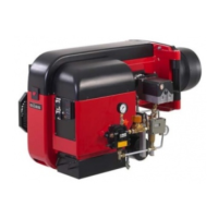
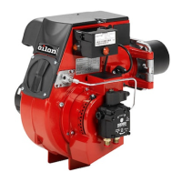
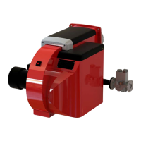
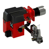
The Oilon T-burners are fully automatic, three-stage burners designed for various heating appliances such as hot water boilers, steam boilers, air heaters, and thermo fluid boilers. They are suitable for use with heavy fuel oil (viscosity up to 380 mm²/s (cSt) at +50 °C, or up to 700 mm²/s (cSt) at +50 °C with electric tracing) and can temporarily use light fuel oil.
The burner's operation is controlled by a sequence switch and a servomotor. The process involves:
- Combustion Air: A fan provides high and steady air pressure for efficient combustion. The servomotor adjusts the air supply according to fuel demand.
- Pre-ventilation, Purging, and Ignition: Before ignition, the burner undergoes pre-ventilation (fan at full load to exhaust fumes) and purging (flushing nozzle valves and the utilization circuit, preheating the nozzle valve, and ensuring adequate oil temperature for atomizing). During purging, solenoid valves (NC) are closed, and solenoid valve (NO) is open, allowing oil to flow through the stage-1 nozzle control circuit but returning to the tank due to insufficient pressure to open the nozzle. After purging, the servomotor sets air dampers to stage-1, solenoid valve (NO) closes, and oil flows from nozzle 1. Spark electrodes ignite the oil spray, and the burner operates at stage 1.
- Atomizing: A preheater raises the oil temperature to achieve sufficient viscosity for atomizing, controlled electronically. Atomizing pressure is provided by the burner oil pump.
- Staged Operation:
- If boiler temperature/pressure exceeds stage 2 set value, the burner stays at stage 1.
- If boiler temperature/pressure falls below stage 2 set value, air quantity increases, solenoid valve for stage 2 opens, oil is delivered to nozzle 2, air dampers move to stage 2 position, and the burner operates at stage 2.
- If boiler temperature/pressure falls below stage 3 set value, air quantity increases, solenoid valve for stage 3 opens, oil is delivered to nozzle 3, air dampers move to stage 3 position, and the burner operates at stage 3.
- When boiler temperature/pressure exceeds stage 3 set value, the burner reduces to stage 2 or 1.
- When boiler temperature/pressure exceeds stage 1 set value, the burner shuts down (air dampers close).
Important Technical Specifications
General:
- Burner Control: Fully automatic 3-stage.
- Applicable Fuel: Heavy fuel oil (max. 380 mm²/s (cSt) at +50 °C, or 700 mm²/s (cSt) at +50 °C with electric tracing), temporarily light fuel oil.
- Minimum Viscosity for In-let Oil: 1.5 mm²/s (cSt).
- In-let Oil Temperature: 60 to 100 °C.
- Oil Filtration: Max. 125 μm before the oil pump.
- Preheater: Oil preheated to atomizing temperature, electronically controlled.
- Heat Cartridges: Oil pump and solenoid valves equipped with heat cartridges.
- Additional Heating: Burner pipes equipped with trace heating.
- Heavy Fuel Oil Atomizing Viscosity: 14 to 16 mm²/s (cSt).
- Light Fuel Oil Atomizing Viscosity: 1.5 to 12 mm²/s (cSt) at +20 °C.
- Oil Atomizing Pressure: 25 - 30 bar for heavy fuel oil, 20 - 25 bar for light fuel oil.
- Number of Nozzles: 3, controlled by separate solenoid valves.
- Burner Max. Turndown Ratio: 1:2.5 (100 - 40%).
- Combustion Air Fan: Provides sufficient air pressure for efficient combustion.
- Required Combustion Air Quantity: 15 m³ per burnt kilo of oil.
- Servomotor and Compound Regulator: Controls burner capacity and air/fuel ratio.
- Operating Temperature: 0... +45 °C.
Burner Models (RP-150 T, RP-250 T, RP-280 T):
- Weight: RP-150 T: 152 kg; RP-250 T: 181 kg; RP-280 T: 182 kg.
- Capacity kW: RP-150 T: 680-2700; RP-250 T: 650-3200; RP-280 T: 900-3500.
- Capacity kg/h: RP-150 T: 60-240; RP-250 T: 58-282; RP-280 T: 80-308.
- Control Unit: LAL 2.25 / LOK16 / PLC.
- Oil Pump: TA2 for all models.
- Oilhose Connection (suction/return): R ½".
- Degree of Protection: IP44.
- Control Voltage: 230 V (-15%... +10%), 50 Hz, 1-phase (other options available: 230 V 60 Hz, 110 V 50/60 Hz, 380-420 V 50 Hz, 440 V 60 Hz, 690 V 50/60 Hz, 3-phase).
Burner Motor Output, Current, Efficiency, Speed (examples for 380 V 50 Hz):
- Output kW: RP-150 T: 5.5; RP-250 T: 7.5; RP-280 T: 7.5.
- Current IN [A]: RP-150 T: 10.5; RP-250 T: 14.7; RP-280 T: 14.7.
- Efficiency [%]: RP-150 T: 87.6; RP-250 T: 85.1; RP-280 T: 85.1.
- Speed r/min: RP-150 T: 2855; RP-250 T: 2915; RP-280 T: 2915.
Preheater Capacity and Current (examples for 380 V 50 Hz):
- Capacity kW: 12 kW for all models.
- Current A: 17.4 A for all models.
Control Unit LAL 2.25 Technical Data:
- Mains Voltage: 230 VAC -15 / +10%.
- Mains Frequency: 50 - 6%...60 Hz +6%.
- Power Consumption: 3.5 VA.
- Fuse, built-in: T6.3H250V, IEC 127.
- Fuse, external: max 10 A.
- Electromagnetic compatibility EMC: 89/336.
- Permissible inlet current to terminal 1: 5 A continuous; instantaneous max. 20 A.
- Permissible load of control terminals: 4 A continuous; instantaneous max. 20 A, in total max 5 A.
- Required switching capacity of switching devices: 1 A between terminals 4 and 5.
- Degree of Protection: IP 40.
- Permissible ambient temperature: -20...+60 °C.
Flame Detector Technical Data:
- Min. required detector current with 230 VAC: 6.5 μA.
- Max. possible detector current: 25 μA.
- Instrument's +pole to terminal: 22.
- Cable run to detector in the same cable as control lines: Not permissible.
- Cable run to detector with a separate cable in cable duct: RAR7: 30 m.
- Shielded cable (insulated shielding): RAR8: 100 m.
Usage Features
- Automatic Operation: The burners are fully automatic, simplifying operation.
- Staged Capacity Control: Three-stage operation allows for efficient adjustment to varying heat demands, optimizing fuel consumption.
- Electronic Temperature Control: The preheater's electronic regulator ensures precise control of oil atomizing temperature for optimal combustion.
- Safety Features: Includes pre-ventilation, purging, and lockout indications for various fault conditions (e.g., extraneous light, air pressure signal loss, flame signal loss, motor failure, ignition failure).
- Adjustable Components: Capacity, combustion air, pressure drop in the combustion head, burner head position, oil pump pressure, and preheater temperature are all adjustable to fine-tune performance.
- Hinged Design: The burner can be hinged to the left (standard) or right, allowing for easier access during maintenance.
Maintenance Features
- Annual Servicing Recommended: Regular servicing ensures trouble-free operation.
- Detailed Maintenance Schedule: The manual provides a comprehensive list of annual checks, including:
- Inspecting and changing burner head extension and diffuser disc.
- Cleaning and checking ignition electrodes.
- Changing oil nozzles if worn or damaged.
- Checking and cleaning the flame detector.
- Cleaning filters (more often if circumstantial conditions require).
- Checking and retightening air damper lock screws and servomotor axle lock.
- Lubricating joints on adjustment rods.
- Checking oil pump capacity.
- Cleaning the burner from dust and moisture.
- Regular flue gas measurements.
- Cleaning the oil tank every 4-5 years.
- Troubleshooting Guide: A detailed table helps identify possible causes and actions for various fault conditions, such as start failure, motor failure, ignition failure, no flame establishment, oil pump failure, lockout after flame establishment, oil leaks, premature flame establishment, and flame monitoring faults.
- Component Accessibility: Instructions for dismounting the combustion head and changing the burner motor are provided, facilitating component replacement.
- Oil Filter Cleaning: Clear instructions for cleaning the oil filter are included.
- Use of Original Spare Parts: Emphasized for reliable operation.
- Safety Warnings: Prominent warnings regarding electrical hazards, hot surfaces, inflammable materials, and the importance of wearing hearing protectors.
- Control Unit Safety: The control unit is a safety device that should not be opened or altered by unauthorized personnel. It must be completely separated from supply voltage before any procedures.