45393301TH Rev.1
7 /
Oki Data CONFIDENTIAL
1.REPLACEMENT OF PARTS
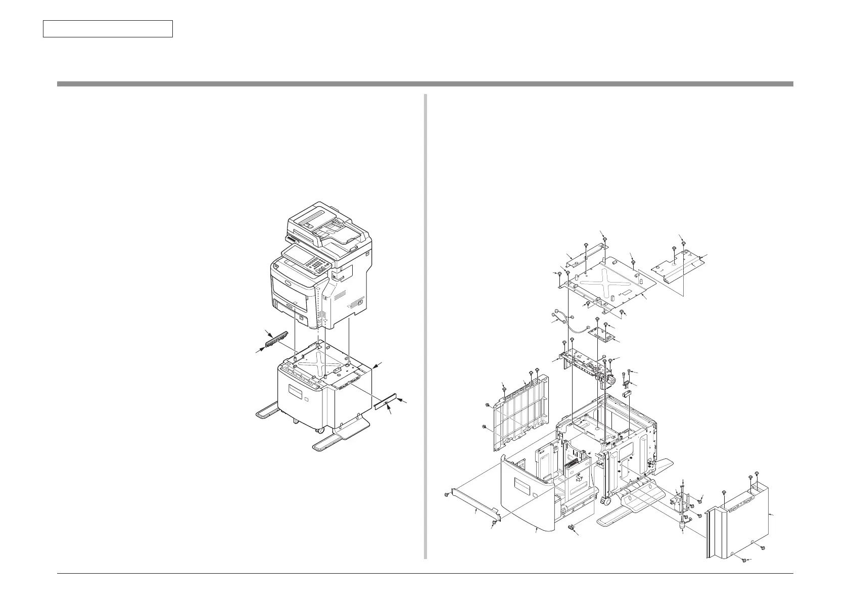
1.2 Part replacement procedure
This section describes the procedure for replacing the parts and assemblies shown in the
disassembly diagrams below.
1.2.1
Board-GOI,Frame.Assy-Hop etc
(1) Remove the Screw (silver,No:41723901)
①
and remove the Joint
②
(2 places),and
remove the LCF Unit
③
from the MFP.
(This procedure unnecessary for B721/B731)
(2) Draw out the Cassette
④
from LCF Unit.
④
⑧×2
⑨
⑩
⑬
⑪
⑪
⑪
⑭
×2
⑫
⑫
⑮
⑯
×2
⑲×4
⑳
㉑×2
㉒
⑥
⑤×5
㉓
㉖×2
㉗
㉔×4
㉕
⑰×2
⑱
①
①
③
(3) Remove the ten screws (silver,No:42920408)
⑤
and remove the Cover-
Side(L)
⑥
,Cover-Side(R)
⑦
.
(If the LCF for B721/B731, remove the four screws)
(4) Remove the four screws (silver,No:42920408)
⑧
and remove the Plate-
Joint(L)
⑨
,Plate-Joint(R)
⑩
.
(This procedure unnecessary for B721/B731)
(5) Remove the three screws (silver,No:42920406)
⑪
and two screws
(black,No:44883906)
⑫
and remove the Plate-Top
⑬
.
(If the LCF for B721/B731, remove the seven screws (silver,No:42920406) and two
screws (black,No:44883906))
(6) Remove all cables
⑮
and connectors from the Board
⑭
.
(7) Remove the two screws (black,No:44883906)
⑯
and remove the Board-GOI
⑭
.
(8) Remove the two screws (silver,No:42920406)
⑰
and remove the Plate-Front
⑱
.
(9) Remove the four screws (black,No:44883906)
⑲
and remove the Frame.Assy-
Hop
⑳
.
(10) Remove the two screws (silver,No:43497603)
and remove the Connector
.
(11) Remove the Claw and remove the Switch
.
(12) Remove the four screws (black,No:44883906)
and remove the Liftup-Motor-
Assy
. Remove the two screws(silver,PSW2W2.6-5C)
and remove the motor
.