45393301TH Rev.1
8 /
Oki Data CONFIDENTIAL
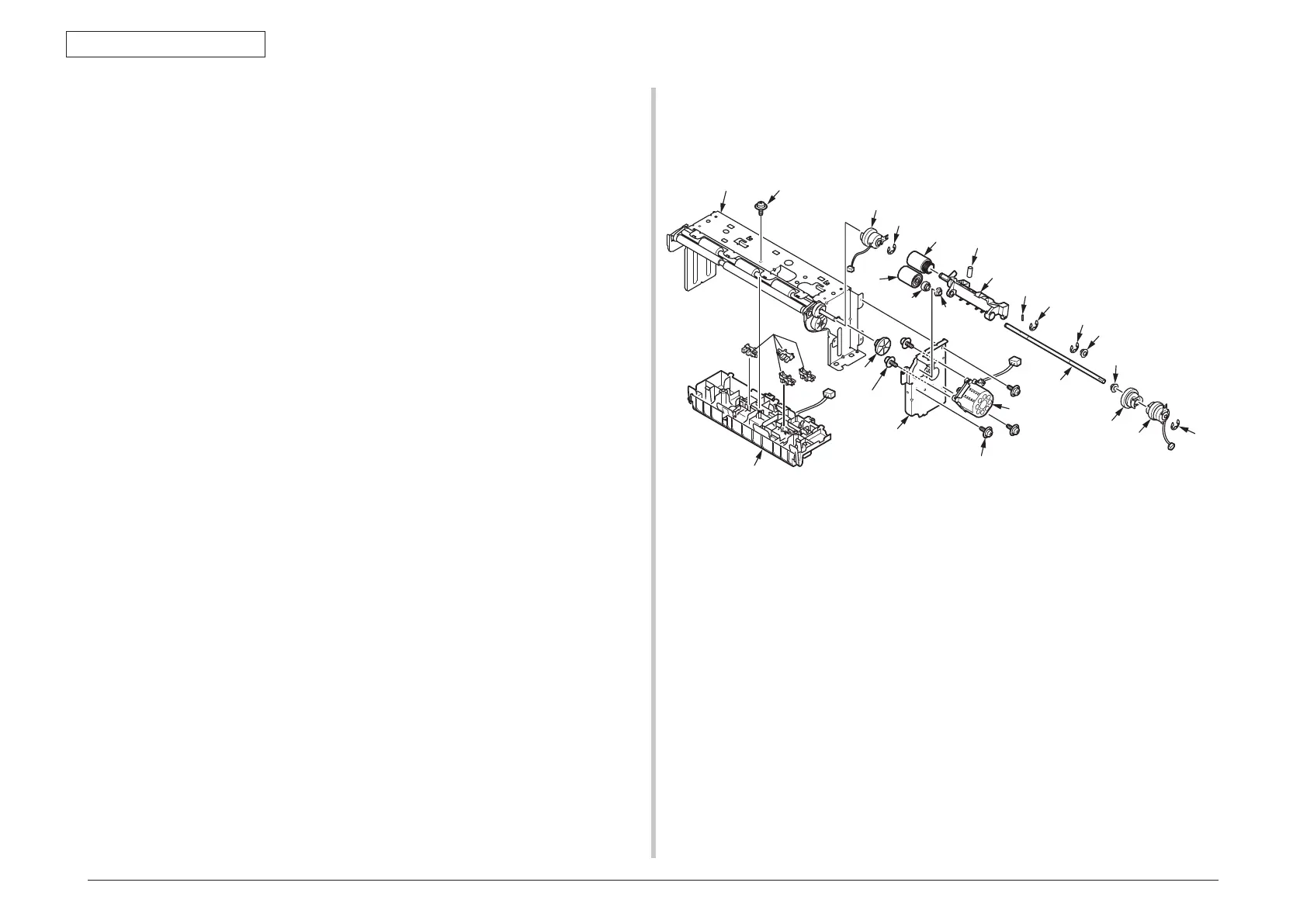
1.REPLACEMENT OF PARTS
1.2.2 Photo sensor
(1) Remove the Frame.Assy-Hop
(
See 1.2.1
)
(2) Remove the E-ring
①
and remove the Hopping Clutch
②
.
(3) Remove the three screws (silver,No:42920406)
③
and remove the Plate-Assy-
Motor
④
.
(4) Remove the two screws (silver,No:42920406)
⑤
and remove the Motor
⑥
.
(5) Remove the Gear-Z21-56
⑦
and Gear-Hopping
⑧
and Bearing-Metal
⑨
.
(6) Remove the Hopping roller
⑩
and Pickup roller
⑪
.
(7) Remove the two E-ring
⑫
and pin
⑬
and Gear-Feed
⑭
.
(8) Remove the Bearing-Metal
⑮
and Bush
⑯
and remove the shaft
⑰
.
(9) Remove the Frame-Assy-Pickup
⑱
.(Pay attention to spring to lose)
(10) Remove the screw (Black,No:42932708)
⑲
and remove the Plate-Hopping
⑳
.
(11) Remove the claw and remove the photo sensor
.(Four places)
(12) Remove the E-ring
and remove the Regist Clutch
.
【
Attention for assembling
】
・
Wiring the white cable of the photo sensor to the mark ”W”of Guide-Hop.
・
When assembling the regist Clutch, same position the notch of the clutch and
bulge of the Plate-Motor.
・
Wiring the cable of the Hopping clutch(Black cable) to the mark ”BK”of Plate-Motor.
When assembling the Hopping Clutch, same position the notch of the clutch and
bulge of the Plate-Motor.
・
When assembling the Motor, four emboss put into hole of Plate-Motor.The direction
of the Motor Cable should ”
↑
”mark of Plate-Motor.
・
To check the three claws and two claws of
is hold by
⑳
.
㉑
③×3
②
④
⑧
⑦
⑰
⑨
⑪
⑩
⑫
⑫
⑬
⑱
⑮
⑭
⑯
⑤×2
⑥
㉒
㉓
spring