EasyManuals Logo

Oki Microline 390 User Manual

Oki Microline 390
174 pages
To Next Page IconTo Next Page
To Previous Page IconTo Previous Page
Page #35 background imageLoading...
Page #35 background image
(2)
Encoder disk
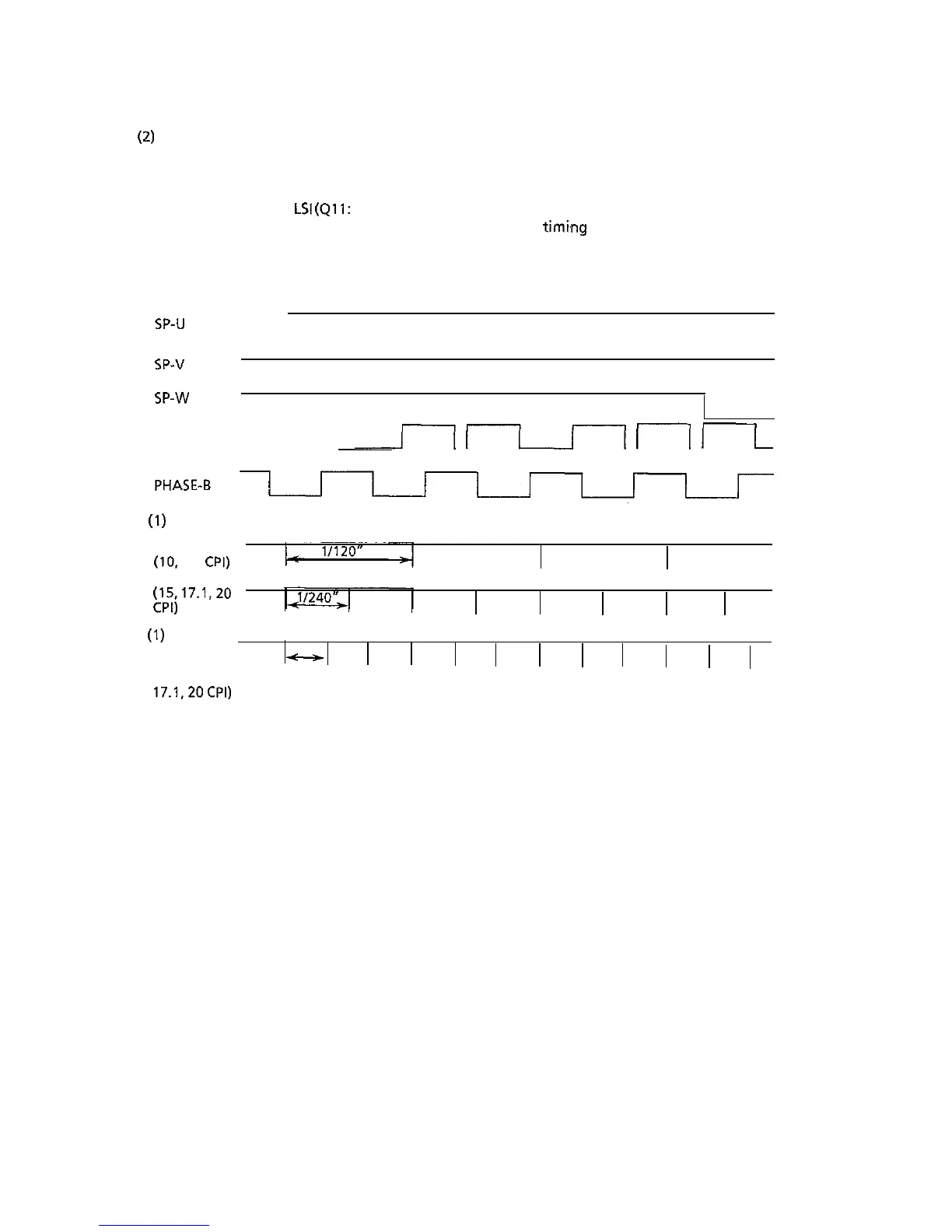
In the operation of the spacing motor, the PHASE-A and PHASE-B signals are generated. When
the encoder disk interrupts the photo sensor.
The motor control
LSI
(911: MSM6990) divides these edge pulse signals in accordance with the
print pitch, and sends the IPT signal to provide dot-on
timmg
and carriage position detection
timing.
SP-u
SP-v
SP-w
PHASE-A
(-1
ru-----l
(1
j--L
(I)
UTILITY MODE
IPT
(10,
12,
CPI)
IPT
p;)
17.1.20
(1)
LQMODE
IPT
-
(10.12, 15,
11360”
17.1.2OCPI)
3-a

Questions and Answers:

Question and Answer IconNeed help?

Do you have a question about the Oki Microline 390 and is the answer not in the manual?

Oki Microline 390 Specifications

General IconGeneral
Print TechnologyDot Matrix
Number of Pins24
Resolution360 x 360 dpi
Print Resolution360 x 360 dpi
Noise Level55 dB
ConnectivityParallel
Paper Handlingcut sheet
EmulationsIBM ProPrinter
Paper Width4 to 10 inches
Weight13 lbs

Related product manuals