2
nd
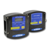
case: CTX 300 without display (except for O
2
, SC and C0
2
)
■ The sensor is operating.
■ Flip the maintenance switch (ref. 1)
into the CAL (calibration) position: the
sensor will send a 2 mA current to the
control unit (Maintenance mode).
■ Verify that the sensor is located in a
clean-air environment. Use the
calibration kit and follow all
recommendations.
■ Connect a voltmeter to the AF+ and
AF- terminals (caliber mV/DC).
■ Wait for the signal to stabilize and
adjust the zero by using the ZERO
potentiometer located on the sensor
pack (Figure 24, ref. 2). The output
signal should be 0 mV.
■ Now inject the recommended test gas
at a flow rate of 30 l/h. Use the
calibration kit and follow all
recommendations.
■ Wait until the signal has stabilized.
■ Read the mV value on the voltmeter
(Figure 23), with the full scale at 1600
mV. Calculate the value to be read as
a function of your test gas.