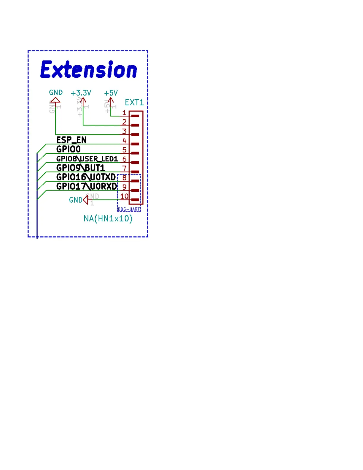
EXT1 connector (GPIO)
EXT1 pin #1 is +5V pin; it is usually used as output you can also power the board from this pins BUT
ONLY IF the USB-C is not connected! It must be regulated 5V power supply, applying more than 5V will
damage the board;
EXT1 pin #2 is +3.3V DC output, it is not recommended to be used as input since you can’t fully power the
board with 3.3V DC (relays require 5V DC);
EXT1 pin #3, EXT1 pin #10 are GND pins, the board has common ground;
EXT1 pin #4 is ESP_EN also known as reset;
EXT1 pin #5 is GPIO0, which a free pin;
EXT1 pin #6 is GPIO8\USER_LED1 – wired to GPIO8, notice that the user LED is on the same wire
EXT1 pin #7 is GPIO9\BUT1 – wired to GPIO9, notice that the button is on the same wire
EXT1 pin #8 and EXT1 pin #9 are GPIO16\U0TXD and GPIO16\U0RXD they can be used for attaching
external USB-serial converter (like ESP-PROG, USB-SERIAL-CABLE-M, or BB-CH340T) to debug the
board; same pins are also routed to the ESP-PROG1 header.
All GPIOs operate at +3.3V levels. This means you should not connect signals with voltage higher than
3.3V to these ports as this will damage the board.
11