GB
F
D
18
○○○○○○○○○○○○○○○○○○○○○○○○○○○○○○○○○○○○○○○○○○○○○○○○○○○○○○○○○○○○○○○○○○○○○○○○○○○○○○○○○○○○○○○○○○○○
○○○○○○○○○○○○○○○○○○○○○○○○○○○○○○○○○○○○○○○○○○○○○○○○○○○○○○○○○○○○○○○○○○○○○○○○○○○○○○○○○○○○○○○○○○○○
○○○○○○○○○○○○○○○○○○○○○○○○○○○○○○○○○○○○○○○○○○○○○○○○○○○○○○○○○○○○○○○○○○○○○○○○○○○○○○○○○○○○○○○○○○○○
I
Se desiderate inoltre alimentare
l’appareccchio con cavi sotto trac-
cia, l’uscita dei cavi è indicata
nella dima di foratura.
ATTENZIONE: le operazioni
seguenti devono essere esegui-
te solo da personale specializ-
zato in accordo con le
normative vigenti.
Verificare che i dati di targa
dell’apparecchio siano corri-
spondenti a quelli della rete di
distribuzione elettrica.
Verificare che non vi sia tensio-
ne ai capi dei fili sotto traccia
durante le operazioni di collega-
mento elettrico. Verificare inol-
tre che l’impianto abbia un’effi-
cace messa a terra e i cavi
siano opportunamente
dimensionati.
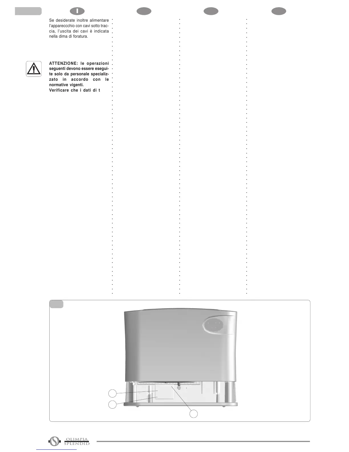
Per collegare i cavi operare nel
modo seguente (fig. 7):
• Svitare le viti ("1") che bloccano
il coperchio morsettiera ("2") allo
schienale del deumidificatore.
• Togliere il cavo di alimentazione
del deumidificatore.
• Collegare i cavi rispettando la
simbologia presente sul
coperchio della morsettiera.
• Riposizionare il coperchio
morsettiera e avvitare le due viti.
If you would like to supply power
to the appliance using chased
cables, the cable outlet is indicated
on the drilling template.
CAUTION: the following
procedures may only be carried
out by specialised personnel in
compliance with the standards
in effect.
Check that the specifications on
the data plate correspond to the
specifications of the mains
electricity supply.
Ensure that there is no voltage
present at the chased wire
endings while setting up the
electrical connections.
Also ensure that the system has
an efficient earthing system and
that the cables are suitably
sized.
To connect the cables, proceed as
follows (fig. 7):
• Unscrew the screws ("1") fixing
the terminal board cover ("2") to
the rear of the dehumidifier.
• Remove the power supply cable
on the dehumidifier.
• Connect the cables in
compliance with the symbols on
the terminal board cover.
• Replace the terminal board
cover and screw down the two
screws.
Si vous souhaitez de plus
alimenter l’appareil par des câbles
encastrés dans le mur, la sortie de
ces derniers est indiquée dans le
gabarit de perçage.
ATTENTION : les opérations
suivantes ne doivent être
effectuées que par du personnel
spécialisé conformément aux
normes en vigueur.
S’assurer que les données de la
plaquette de l’appareil
correspondent à celles du
réseau de distribution
électrique.
S’assurer que les extrémités
des fils encastrés dans le mur
sont isolés de toute tension
électrique durant les opérations
de branchement électrique.
S’assurer de plus que
l’installation possède une mise
à la terre efficace et que les
dimensions des câbles sont
appropriées.
Pour brancher les câbles, procé-
der de la façon suivante (fig. 7):
• Dévisser les vis ("1") de fixation
du cache-bornes ("2") au dos du
déshumidificateur.
• Retirer le câble d’alimen-tation
du déshumidificateur.
• Brancher les câbles en
respectant les symboles
indiqués sur le cache-bornes.
• Remettre le cache-bornes et
visser les deux vis.
Möchten Sie außerdem die
Versorgungskabel unter Putz
verlegen, finden Sie die Angaben
über die Kabelausgänge in der
Bohrschablone.
WICHTIGER HINWEIS: die
folgenden Arbeiten dürfen nur
von Fachpersonal in
Übereinstimmung mit den
gültigen Rechtsnormen
durchgeführt werden.
Kontrollieren Sie, dass die
Angaben auf dem Typenschild
des Gerätes denen des
Stromnetzes entsprechen.
Kontrollieren Sie, dass während
der Anschlus-sarbeiten keine
Spannung an den Enden der
unter Putz verlegten Kabel liegt.
Kontrollieren Sie außerdem,
dass die Anlage genügend
geerdet ist und die
Kabeldurchmesser ausreichen.
Zum Anschließen der Kabel gehen
Sie folgendermaßen vor (Abb. 7):
• Die Halteschrauben ("1") der
Klemmleistenabdeckung ("2") auf
der Geräterückseite lösen.
• Das Versorgungskabel des
Entfeuchters abnehmen.
• Die Kabel entsprechend der auf
der Klemmleistenab-deckung
angegebenen Ken-nzeichnung
anschließen.
• Die Klemmleistenab-deckung
wieder aufsetzen und mit den
beiden Schrauben befestigen.
1
2
1
7
2