103158-01EN [U8998465], Rev. A, April 2012
Configuring the Workstation 9
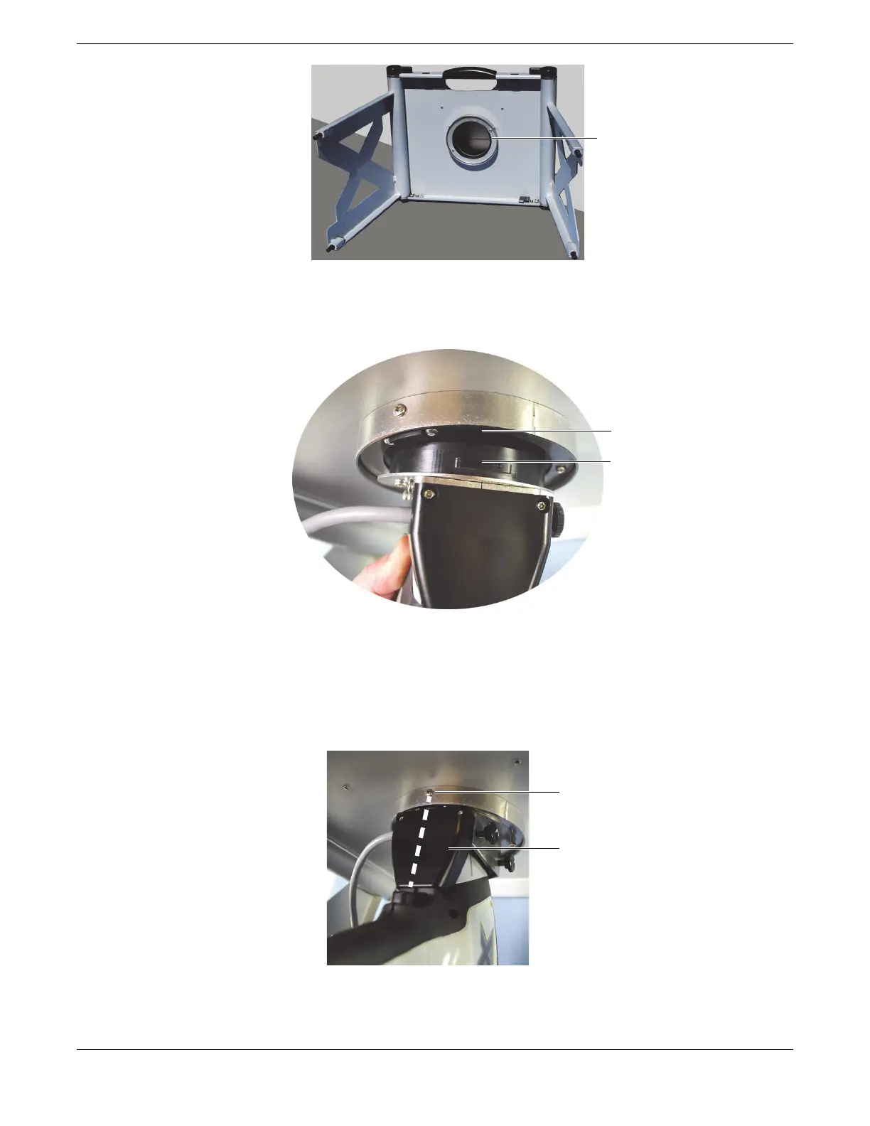
Figure 5-3 Test-stand locking fixture
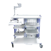
3. Align the large tab of the probe adaptor with the large notch of the locking fixture (see Figure 5-4 on page 9).
Figure 5-4 Alignment with locking fixture
4. Make sure that the probe-adaptor faceplate is flush with the test chamber floor.
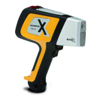
5. Carefully turn the analyzer-adaptor assembly counterclockwise until it locks.
The probe-adaptor plastic housing must be centered with the locking-fixture alignment screw (see Figure 5-5 on
page 9).
Figure 5-5 Analyzer-adaptor assembly installed on the test stand
6. Place the workstation in the upright position
Locking-fixture large notch
Probe-adaptor large tab
Alignment screw
Plastic housing